Pedals
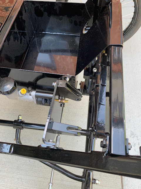
There are two pedals in the Lyka. One to adjust the flow of steam, one to make you stop. They mount to the "Pedal Plinth" provided with the frame. It is a heavy duty piece of steel that bolts between the frame and the Battery Box. Holes are pre-drilled, and mounting hardware provided. I added washers and lock washers. I also Loctited the bolts used for the brake cylinder mounting.
After mounting the pedals, I wrapped the accelerator pedal to keep it from chipping paint as it will be awhile until it gets hooked up.
Rigid Piping
Also in the kit are pre-made rigid pipes with flared connectors and nuts. There are also 3-way units and also a supply of banjo and bulkhead connectors to make up the flexible pieces. A bag of cable clamps round out the supplies.
There are no detailed drawings of the overall brake system, but STW does provide a series of closeup pictures. These provided enough information to get myself started.
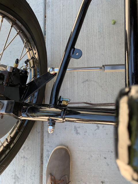
The first thing I did was to mount any hardware. The 3-way connectors attached at the wall next to the master cylinder, at the front near the steering connection, and on the rear axle near the differential. I dislike having connections rubbing against painted surfaces, so I made "stand-offs" using extra nuts. This made sure my wrench would not mess up the finish, and on the rear axle housing, it made sure that the bolt would not impact the axle rotating in the housing.
The main connection at the Master Cylinder. I am not sure all that will go into the "Battery Box' so I wanted to keep the "snags" to a minimum. The pipe going "up" is the long feed to the rear.
And just so no one can tell me I am not consistent - the clamps are also with stand offs especially on the rear axle.
The Game's Afoot -
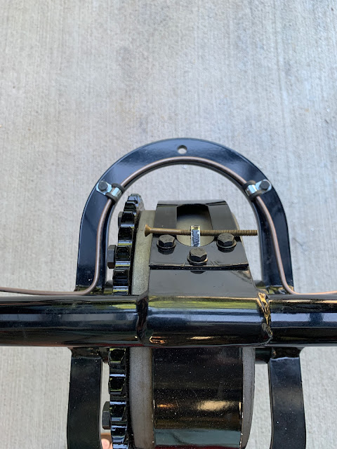
Last but not least is the routing of the rigid pipe around the differential. Now you have to understand that part of the "game" is that STW does not always tell you what is to come. So in the picture of the band that goes around the differential, they just show the pipe sitting there, bisecting the hole. Then the instructions say to "drill a hole" for one of the pipe holders.
OK, I can drill a hole to hold the pipe in place - but what is the other hole for? Well - thanks to Grier, I come to find that the hole is for the Chain Tension Adjuster. If I had not paid attention to that, I would have a conflict - Also - from Grier's Blog, there was a comment that only 5 of the 6 pipe clamps were allocated by STW. That allowed me to maintain symmetry. Something I like to do as often as possible.
Flexible Lines and Connectors
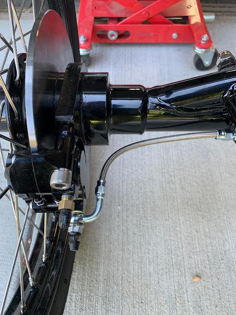
The "last mile" in the brake system are flex lines that tie things together and connect to the calipers at each wheel. STW gives you "just enough" bulk cable to build the 6 flex lines you will need, one for each wheel and two for interconnections. And I mean that - Just Enough - I had 1.5 inches left over. So this is a case where you need to measure about a dozen times before you cut.


No comments:
Post a Comment
Thank you for posting your thoughts on my build.