What its all about

Poppapope's Steam Car

October Activities - Small Projects

Report from STW

I heard last week from Dean at Steam Traction World (STW). He is the Director or General Manager of the company.  I suspect he is also the owner, but I do not know for sure.  The UK has quite a number of different terms for everyday things.  

Dean and I have corresponded and talked over the past two years during my association with STW. I have been somewhat frustrated over the extended time the production is taking and Dean wanted to set the record straight.  

STW has been affected by the last 3 years in much the same way as other industries.  Suppliers have been unable to meet schedules, a number of the foundries they deal with have closed,  people retired or moved on, and production has suffered delays.  

Dean has assured me that the Lykamobile production is getting back on track and he feels that the remaining kits will be produced by the end of the year.  Over the past month I have seen reports and inventory lists for the various kits and I am feeling comfortable with the promise that my investment is not at risk.  Which is good because I am not sure what I could do with a 1/2 a steam buggy. 

Dean sent me some pictures of more boilers under construction.  If this is all of the Lyka boilers, then it looks like there are 8 other Lyka projects out in the world and underway.  It would be great to hear from the other builders and get to know them.  So if anyone reading this blog is currently building a Lyka please let me know and we can compare notes as we finish over the next months. 


Louvers

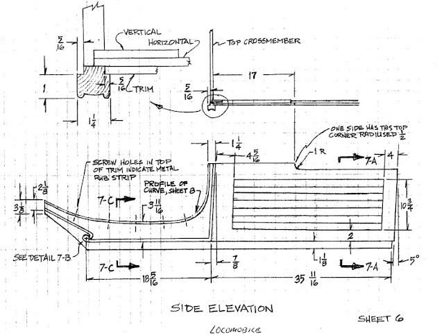
The original Locomobile had a body made of wood panels.  Parts were made from or covered in leather, and the side panels on most models had strips of wood running horizontally on both sides.  These strips resemble louvers but in fact are not functional.   Grier, on his blog, showed that he had found a number of drawings relating to the features on the side panels for both Locomobile and also Mobile (offshoot of the original Loco) models of the time.  


Using these drawings as a guide, I started looking for pieces of wood I could use as louvers.  From what I could determine from previous STW production runs,  the body panels are provided smooth so whatever additional features will have to be added by myself.  I could not find the tear-drop shaped (side view) slats of wood already formed as louvers and I have limited wood shop tools.  I decided to buy some slats that were already close in shape from our local wood-working store.   Then I set up a sanding jig to allow me to get them into a shape closer to what we needed. 


A little more clean up and I have a nice stack of "louvers."   Now it came time to decide on the color scheme.   I had already decided to accent my build with "British Racing Green" (BRG) and some of the engine parts have been painted that color.   I started looking for additional sources for the color and find that there are a number of versions to BRG and so I stayed with type I used on the engine.  This is actually Engine Paint that is high heat and has some ceramic of some type in it.  It went on smoothly and too the gloss top coat very well.   I will put it all aside until the body parts actually come in. 


Well, that is about it for this week/month/quarter.   First snowfall is supposed to happen this evening, I guess Fall and Winter are really here.  I will have limited working time in the garage shop.   Time to work on some of those in-side projects I have been putting off.  


So - keep an eye out once a month or so just to see if I have gotten anything more from across the pond. 

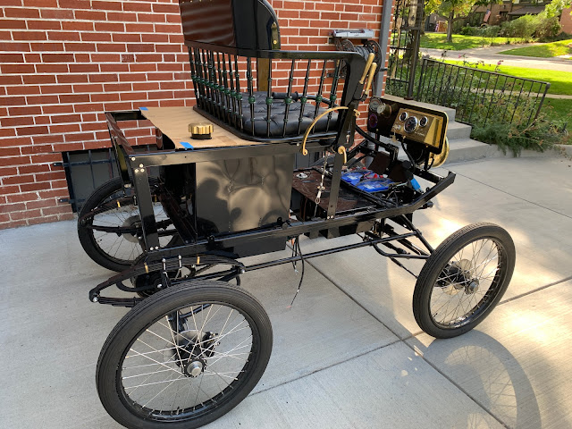
Here are some pictures of the Lyka as I get ready to store her for over the Winter. 


Regards to all - Thanks for reading,

Poppapope
Denver, Colorado USA

Just killing some more time.

 Headlamp Bracket

A while ago I covered the reconstruction of a Solar 800 Headlamp.  

https://poppapope-steamcar.blogspot.com/2023/03/finding-things-to-do-waiting-for-boiler.html 

At the time I decided to electrify it and after shining it up, I put it aside until I could figure out how to mount it on the front of the car.


Taking a cue from Grier, I focused on getting some type of mount that attached to the point where the front of the frame and the front leaf spring came together. 


When I got the frame kits from STW, the studs provided for bolting the frame to the chassis were about 1/4 inch too long.  At the time I took the easy way out and used some larger nuts as big spacers to eat up the slack.  Coming back and looking at it, I decided to try for a bracket that would fit on the front edge of the assembly and was made of 1/8 inch steel. This way it would clamp over the existing plates and I could remove the "spacer nuts" as the clamp would use up the excess.  


So - Where to get a bracket?  

I scoured Ebay, Etsy, Model-T sites, Brass Era sites over a couple of months.  I never found an 8" Headlamp bracket that I could use as a starting point.   I studied the blog entries on Grier's blog, 

https://210doghouse.blogspot.com/2018/03/front-headlamp-mount-part-1.html 

where he modified one to mount on his Lyka.  

After assessing my welding skills (none) I went on a hunt for someone to help me out.  I talked with a couple of fabricators here in Denver, and found that unless I was doing a large project they did not have the time.  So I looking into the local "Steel Yards" to see if I could find anyone there.  In the past I have found that many suppliers of material, wood, steel, plumbing, etc have people woring there who are craftspeople and will do small jobs.  

I found a place - Altitude Steel - in Denver that was willing to supply and fabricate my little bracket. 

(Shameless Plug)


 I gave Jake some sketches on graph paper - napkin cad - and he was able to get my bracket built in a very timely manner.   It turns out that my measurement on a crucial portion was off by a 1/2 inch, and he graciously modified the initial bracket to fit.  (no extra charge).   I will use him again for any other steel projects, on the car or off. 

Here is the bare steel bracket, as delivered,  only some minor cleanup on the two rods that insert into the headlamp was needed.  It all fit, but I wanted a little play to make removal easier.  There are a pair of bolts (set screws) in the lamp to lock it all down so I am not worried about it rattling away. 

The bracket - 


Rough Fit - I opened the bolt holes a bit to allow minor side to side adjustment. 

Primer and Paint - Automotive Gloss Black with Gloss Clear Coat.  


Fit to the front mount - I was a little concerned about getting everything tight again, especially the original use of the bolts which was to afix the chassis to the leaf-springs.  However, the bracket was just tight enough to snug everything down.  


 And a fit with the Headlamp - 


Next I dressed the power cable,  and of course - tested the lamp. 
I think that the "focus" on the beam will take a little fiddling to get setup.


 Well, that's it for this week.   I have not heard from STW about any lights at the end of the tunnel but I know that reports of how busy they are on the production floor mean that mine is not the only project behind the 8-Ball.  

It is the end of September now, and fall-winter here in Colorado means that painting and finishing get more difficult as well as your fingers get stuck to bare metal!  

So - I have set my target "First Steam-Up" for our Memorial Day - the last Monday in May, 2024. 


Unless of course - I get a surprise package before then. 


Regards to all.

Thanks for reading. 

Poppapope
Denver, Colorado USA


More from Kit 18 - The Chain Drive

The Chain Drive 

Kit 18 was a bit of a hodge-podge of parts and sub assemblies.  There was the Wire Loom and Electronics, and the the Water Glass (which was just set in a box for when the piping actually showed up). Also in the kit was the Chain Drive and stiffener.  Finally was the Steam Regulator, and cable assembly.  Most of these pieces and parts were not usable until the Lyka was further along. 

However, after sitting and looking at the big empty hole where the boiler and burner belonged, I decided to fit the chain, at least for now.  I think this was a goo idea as it was a couple of links too long and required quite a bit of playing with.  If I had waited until the boiler and burner were installed, I would have needed to work under the car on my back.  As it was I could get everything fitted easily and can remove/replace it quickly when the boiler comes in. 

Based upon Grier's experience I went to the McMaster-Carr website and ordered a 1/2 link of a 12B chain.  This turned out to be necessary.  

First step -  Use a string to help pull the chain around the small-end engine sprocket. 


 Then loop the chain around the differential,  and do a test fit for length. 


A side view - pretty droopy. 


Here is the 1/2 Link along with the coupler provided by STW. 


Here is the 1/2 link installed after removing the excess.  You have to make sure you end up with the right parts next to each other. 


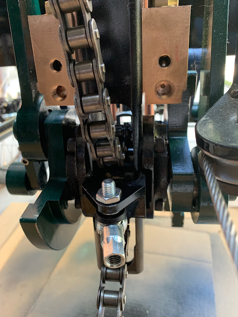
Chain Tension-er -  There are two brackets that get a ball joint and then a tension rod is run between them. One ball joint fits to a small bracket in the engine mount tube that is in-between the chain runs.  The mounting bolt must be ground down and a 1/2 thick nut used in order to avoid interfering with the chain travel. 


After grinding down the excess bolt length and pulling the chain just tight enough, The droop is gone and the chain will clear the bolt. 


So finally, the chain in place between the differential and the engine, checking the alignment.  If I need to remove it to install the boiler and burner system, I will be able to hook it back up without a lot of crawling under the car. 


Leaving it hooked up for now.  


Thanks for reading,


Regards,

Poppapope
Denver, CO USA


The Boilers are a-coming - soon?

 Boiler update - 

I heard from Steam Traction World that the boiler design has finally been approved and the boilers were in production.  It seems that since Brexit, there are now TWO agencies to make happy, one in the EU and one in the UK.  They each have similar requirements, but must be dealt with separately. 

Dean, the director of STW was kind enough to send me a picture of the boilers underway. 

Hopefully, now that the details are worked out, the remaining kits can get organized and packaged without further delay.  We have stalled waiting on the boilers with only piddling stuff to work on for the past year.  It will be good to back on track.  


Brake Light 

During tests of the electronic package I designed, I discovered that the switch I had configured on the brake pedal was not going to work.  The amount of movement required for switch contact was only about 1/8 inch.  I am concerned that the vibrations in normal travel will result in false indications.  

I found a more conventional brake switch that has a spring-loaded system where the contact is made after about 1/2 inch of travel.  

The original attempt: 


I removed that bracket and built a new one to hold the larger switch.  The switch and bracket both have a little bit of "springiness" to allow the play in the pedal.  


Playing with the Sight Glass Assembly

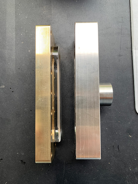
A part of Kit 18 was the Sight Glass Assembly.  This consisted of two very hefty metal parts, one brass - one stainless, a glass lens, gaskets and a sensor system for the water level.  

The hole in the back is for the sensor.


Steam Traction World had provided Black Oxide bolts, I replaced them with Stainless & Washers.


Water level sensing is done by using an IR (infrared) led and sensor.  The prism lens changes how the light refracts when immersed in water.  The change in levels is sent to the circuit box (in background) where it will open or close a relay (depending on the change) - if the relay is open, the flow of electricity to the burner relay is interrupted.  This circuit is in series with two other control points, the pressure switch and the burner enable switch (on the dashboard).  

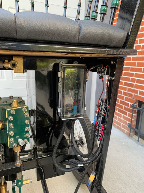
The water level sensor control. - Three Off-the-Shelf parts in a small plastic box.

The end result is three places that need to be in agreement in order to fire the boiler.  I am also contemplating another level sensor, one that also had high and low points, in order to control the water bypass valve. 


However - all of this goes in AFTER the boiler. So we will just have to keep on working on the little pieces that will help it go all together. 


Thanks for reading,

Jim Pope
Denver, CO USA