What its all about

Poppapope's Steam Car

Running on Air

 On a search for clicks and clacks

I took some time and checked out the engine looking for scrapes and marks showing interference.  I did find that one of the piston rod glands was a little loose, and the cross-head was hitting it at TDC.  A quarter turn and clearance reappeared.  I also found that the pump rods were making a little clicking noise when changing direction.  There was about 1/16 inch of slop.  I am not sure if that is a something I need to worry about. 

After adjusting, I set up the compressor to slowly increase the output to 60 PSI and then just run until it had run down.  


It started moving at about 20 PSI. 


Back to twiddling my thumbs.  


Thanks for reading,

Poppapope
Denver, CO USA

Kit 14 - Engine Controls, Timing the Engine - Running for the first time.

 Kit 14 - Reversing Gear, Water Pump Bypass.

I contacted STW in January to see what progress had been made on my remaining kits.  I received word that while the boiler and related kits were still underway, Kit 14 - The Reversing Lever, Parking Brake and Water Pump Bypass were ready to ship.   

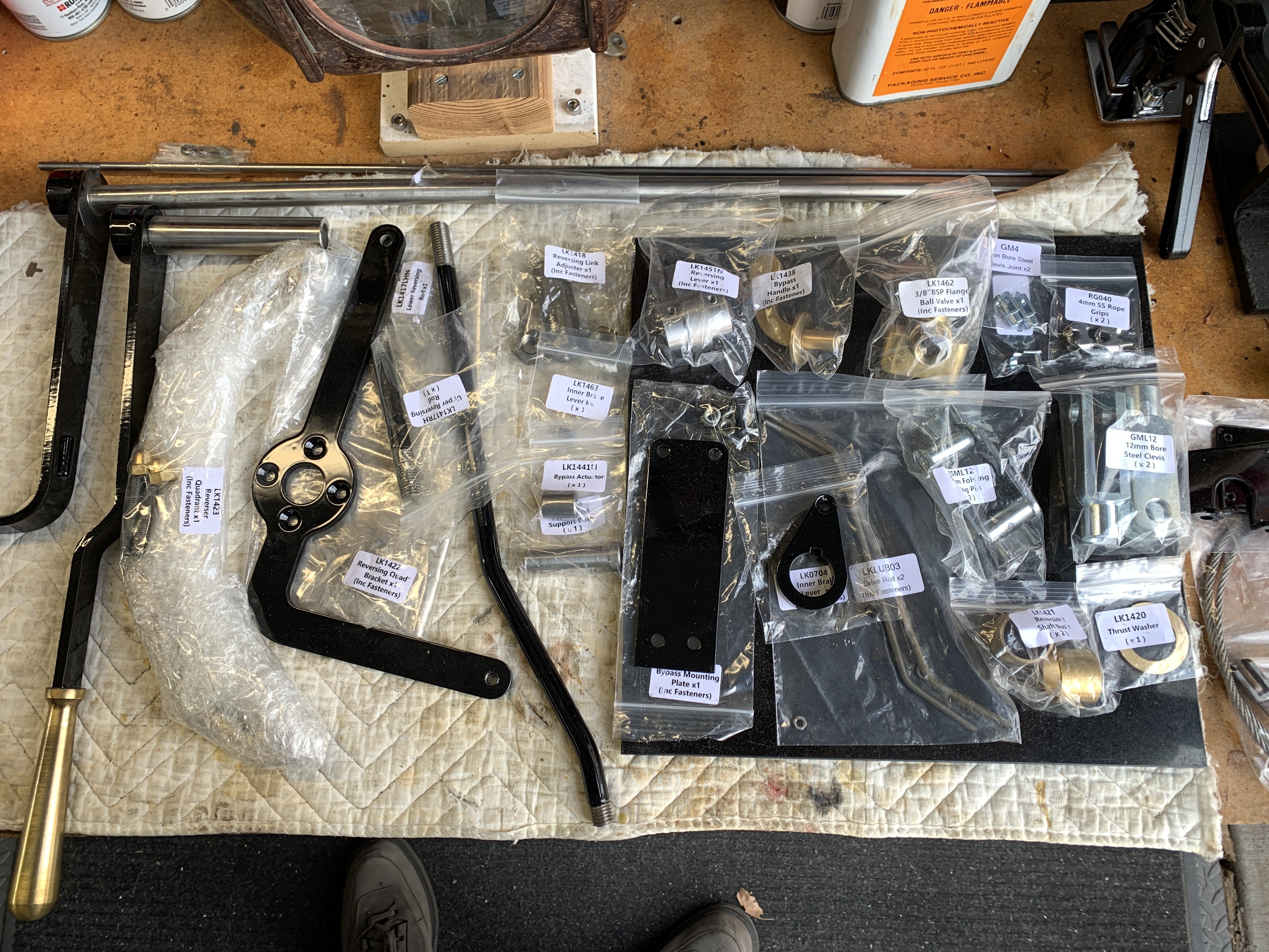
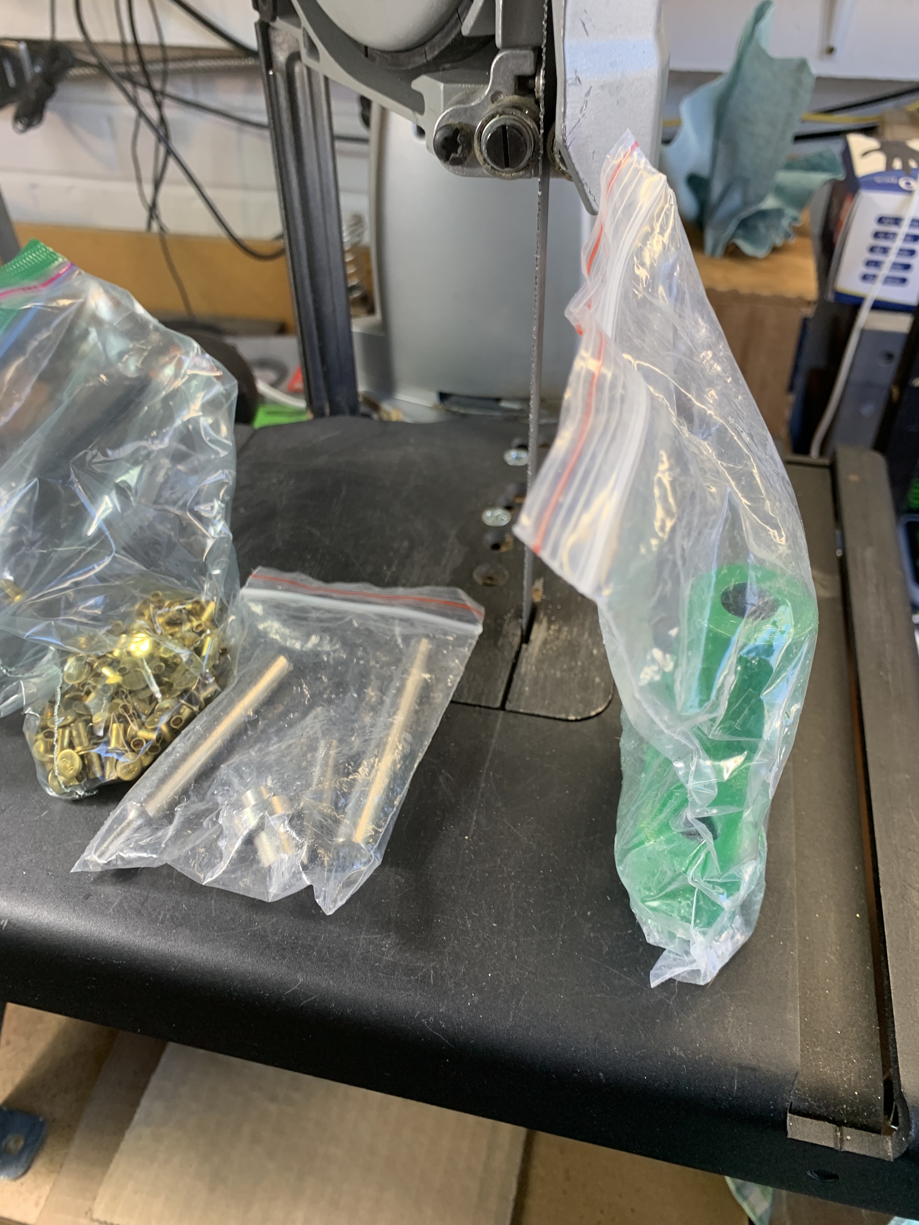
I received the kit in late January and separated the kit into sections, sending some parts out to get powder coated.   


Two weeks later the parts are back, so now I need to wait for warmer weather. 


While I waited on the weather,  I buffed and polished the brass "quadrant".

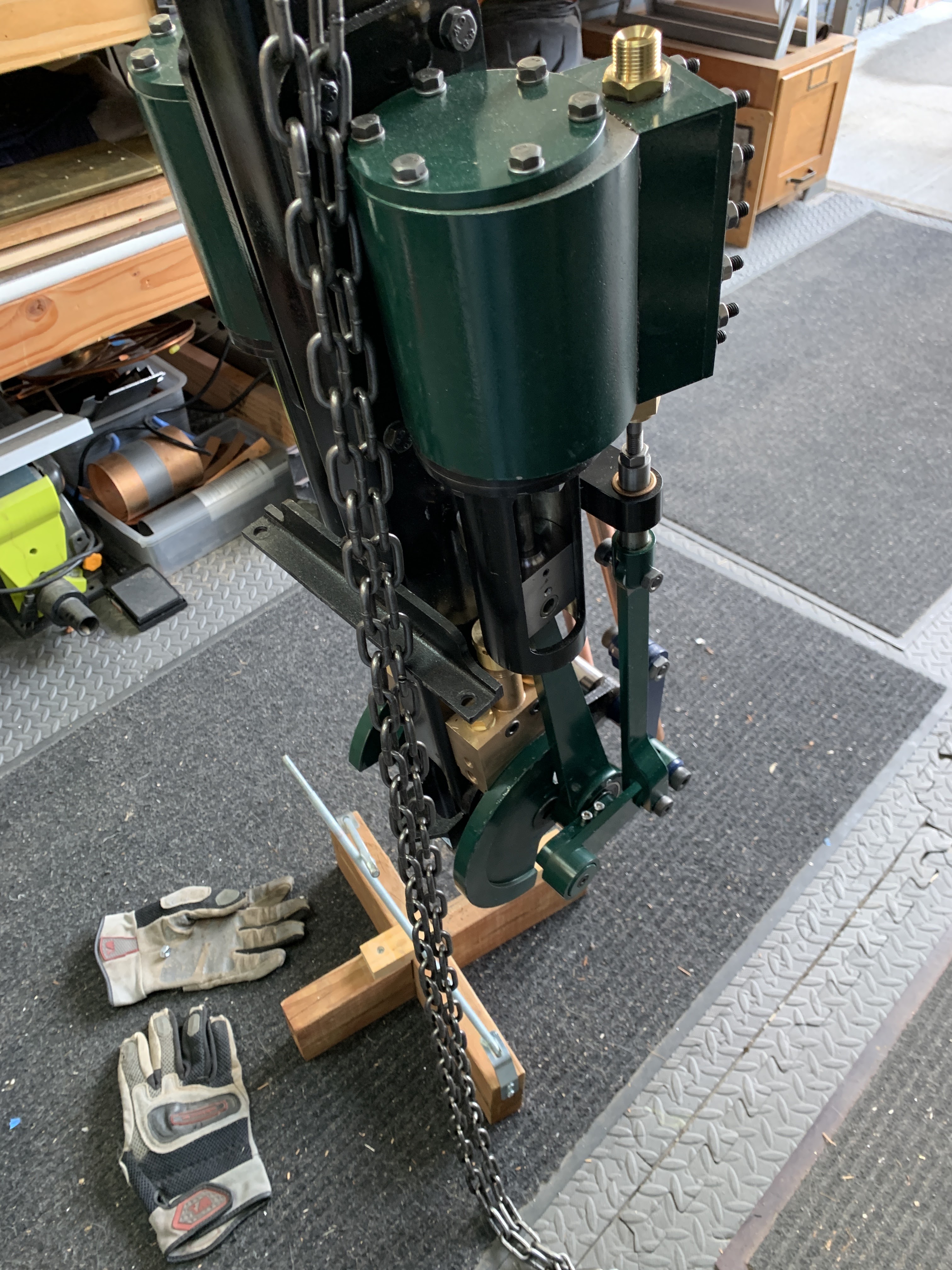
So now it is early in March, and we have a few days above 50 degrees.  The engine is in place, the differential has been re-assembled, and parts are ready for assembly. 


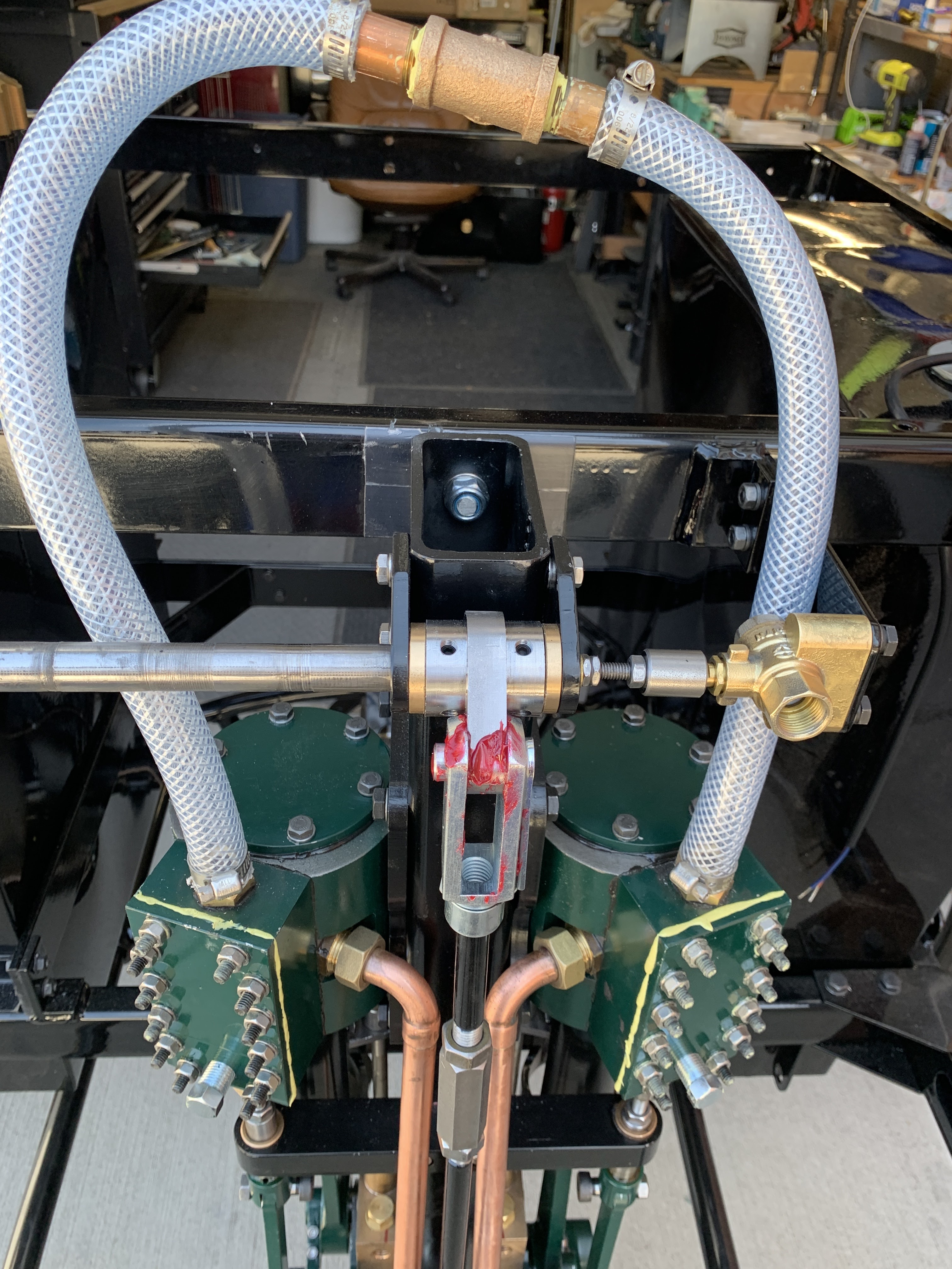
First was the supporting bracket. 


Then the Brake Lever was installed.  Followed by the "Reversing" Lever.   The shafts fit inside each other and finish with the rod for the pump bypass. 


The far end of the reversing shaft ends at a pair of bushings in brackets with the upper end of the reversing rod.  It took a few shims/washers on the brackets where they attach to the main engine tube to make things line up.   I also needed to clean up the interior of the revering shaft to make the interior bushing fit. 


Then the Pump Bypass Valve is mounted on it's bracket and the control rod inserted.  The overall length is about 1/4 inch too long.  So a little grinding and adjusting the angles makes everything line up.


Then the lower control clevis for the reversing arm needs to be added to the shaft and connected.  This required a partial disassembly of the linkage, luckily very easy at this point. 

In preparation for the attempt to run on air, I found the plug I needed for the face plate on the slide valve chest.  Turns out that piping in this part of the Lyka is BSPT  (British Standard Pipe Tapered).   I have found that McMasterCarr carries all sorts of goodies and I am confident that going forward I will be able to adapt and tweak te piping system.  But for now I will just leave things alone. 

Timing The Engine

Now that I have the reversing linkage in place,  I need to setup the timing on the engine.  I took the covers off the valve chests and exposed the valve slides.  I made sure that the slide would still "float" meaning move horizontally against the face of the valve openings, but also would NOT move vertically between the nuts on the valve rods. 


The "Timing" process is not difficult, but can be tedious.  You bring the piston to TDC and adjust the slide rod so you just see the opening behind the slide. Then you move the piston to BDC and check the lower opening.  The trick is to average the opening size between the two positions.   After setting both pistons in the same way, you have to move the reversing linkage to the other position (reverse) and check again.  Then go back to the first (forward) and verify you did not mess anything up.  

After doing this, I used SteamSeal and attached the tops of the cylinders, adding washers.  I should not need to open those again. 


I used RectorSeal 5 on the face plates as I may need to go back in to those. It works well and stays semi-soft.  I will replace it with SteamSeal a little later. 

Next I put together a manifold from some pipe nipples, a pipe "T", and a compressor fitting all together with a couple of pieces of reinforced flexible tubing.  I used some ring-clamps to keep anything from popping off under pressure.  

Running on Air

I have a small compressor with a tank that is about 2-3 gal. - I use it with nail guns for carpentry and such.  It does not really have the capacity to be used with "air tools" like grinders and such.  

Those facts aside,  I used it to power the engine for the first time.   The first time, I drove the engine at about 60 PSI.  The engine gave a little "squeak" and started right up.  I could only get about 30 seconds out of the system before the pressure dropped.   So I worked up a process of running the engine at 25PSI for a longer period on later runs.  

FIRST RUN - 

60PSI.  When I reversed, you can see the linkage stop because the full pressure caused it to  lock up.  It real life, I think that the driver would let off on the pressure before shifting.  


 I made 6 runs today, and varied the pressure to see how things acted. 


I noticed some minor "clicking" - not sure it is a full "knock" but I will spend some time looking for the sources.  

More views and runs - all at about 25-30 PSI.  I am surprised how smoothly it all is going.  


Finishing up - 

I know that running on air is much different from running on steam.  My experience with smaller engines is that Steam will run much smoother.   

So -I will make a few more short air runs and and look to see if there are any real knocks or interferences to worry about.  


Thanks for reading - 

More to come,
Poppapope
Denver, CO USA


Fixing the FUBAR

 Differential and Parking Brake

When I first assembled the differential,  I was in the fog of "Oh Boy - I Have a Toy to Build".   And I really did not understand the relationship between a "key" and the shaft/gear.   I was in a hurry, and used a grinding wheel to make the fit on the keys for the main gears in the differential.  This resulted in the keys being rounded in one direction.   During the last 6 months, I noticed that I had "play" in the wheels back and forth.  Now some of this is the connection between the Main Drive gear and the internal gears that allow for the differential to do its job,  but it just seemed loose.   

Since I had some time to kill, and a minor masochistic streak, I decided to strip it down and replace the keys.    In the picture below you can see the 4 keys on the top and one of the new keys on the bottom. 


 I made sure the keys were nearly an interference fit that needed a little "help" getting into the key-ways. This was the cause of a bit of an issue with the second gear.  It is already incredibly tight, and having to wedge the keys in just added to the verbal exclamations during assembly.  I also had a chance to add more grease to the mix,  better safe than sorry.  


It may not look like it, but the ends of the shafts DO NOT make contact. 
 

Parking Brake

When I disassembled the differential,  the parking brake lining had separated from the outside band.  The construction adhesive had failed.  I had also ignored the advise of others an neglected to rivet the band. 

Grier (on his blog) had shown using a Ford Model A rivet set to attach his band.  I searched a Ford parts website and picked one up along with a pack of rivets.

The kit has a bit for countersinking the rivet heads below the surface.   This made for a very easy job. 


The end result of these two days was that I spent the about the same amount of time as I would have when I first assembled the differential and brake, but it has also reinforced the knowledge of how the parts went together.  

A VERY MAJOR difference between the Model Engineering / Boat Building world and this one is that in the model world we permanently affix a lot of parts and in the full size world, everything must be able to be disassembled.

This thought process goes into all the steps - 
"Does this need to be maintained?" 
"What must happen in order to do that?"
"Did I already affix something that must be removed later?"
Usually it boils down as to what color Threadlocker - Blue or Red.   I must admit that I am using more Blue than Red.  

Now that I have mounted the Engine and rebuilt the Parking Brake I can move on to the process of installing the reversing linkage, and maybe running the engine on air. 

Thanks for Reading,

Poppapope
Denver, CO USA


Installing the Engine

Trying not to drop it. 

The engine was built, piece by piece, on a mount that I built from 2x4's that used threaded rods to hold the center post vertical.  When complete it weighs in at about 100lbs.  A bit unwieldy to just pick up and place in the chassis.  


 I decided to use my chain winch to pick it up and maneuver the engine over the frame and into place. I used a brass rod thru the guide brackets and used the winch to get it up in the air. 


Due to a slight mis-align in the horizontal mounting bracket, the upper bolt hole did not line up when first set into the chassis.  This would have caused issues with the chain alignment in the future.  I used a couple of washers and a piece of aluminum angle as a shim to bring things into proper position.  Then added lock washers and tightened everything up. 


I used a piece of aluminum bar as a straight edge along the side of the drive gear to check the alignment of the differential and the lower gear on the engine.  Looks perfect to me.  

Next I fix some issues on the differential and the parking brake. 


Thanks for reading,
Poppapope
Denver, CO
USA

Finding Things to do - Waiting for the Boiler.

March 2 

Winter is winding down.  Days are getting over 50 degrees, which is nice because I work with the garage door open and the chassis wheeled out on the driveway. 

I am sure that others have the same experience with garages over the winter.  You tend to just dump things in there with the plan to go back and straighten everything out "later".  I am no different.  Stuff I think I might use gets piled up and eventually it gets difficult to move.  

So I spent about 3 days cleaning out the boxes and putting away all the tools that got dumped after use.  Then I uncovered the headlamp I got for a song on EBay.  Now I know that the original Model 1 (the Stanley Stanhope Model 1 from Locomobile - that which my little girl is based upon) - did not have a headlamp.  It just had side lamps.   

However,  many of the examples I have seen, both of "originals" and replicas, have one and sometimes two headlamps.  So - after looking around for a while I picked up an 8 inch SOLAR that looked to be in reasonable condition.   Well - If I had looked at the pictures a little better, I would have seen some cracks. To be fair the ad did say "some repair may be needed".

 A first look - Honest "patina" - some dents visible.


 The lens is totally intact. 

So is the reflector.


I got nervous about scratching the back of the reflector, so I wrapped it in plastic wrap.  


Here are the cracks that I found. Wonder if I can solder them?

 The first step in trying to repair the cracks was to remove the old patina and get everything down to clean brass.  I found that the "flap" was moveable, and spent a bit time cleaning the edges of the cracks in the hopes that solder would stick efficiently.  

I looked into types of solder and found a company called "Muggy Weld" that made alloy solder rods and flux.  I chose their "Super Alloy 1" for a variety of metals.  It has a low melting point.  Since I was looking to secure the "flap" and I did not think that it would get very hot (I was planning on converting to electric), the low melting point made it easier to work with.  

As you will see, I am not as good as I thought I was. 


Not the smoothest solder job I have ever done.

I used a Dremel with a sanding disc to smooth out the big blobs.


After cleaning up the solder job, I worked on the remainder of the shell.  Even though the cracks are sealed and smoothed,  it looks like the back of the light is going to have a fair amount of visible dents.  I decided to paint the back dome a gloss black.   This might be a little different than standard, but it will look pretty good along with all the other gloss black on the car. 


So - on to the interior.   I wanted to change acetylene burner to an LED bulb.  I also wanted to keep as much of the interior structure as possible.    I went to Restoration Supply Company and found a small adapter that would attach to the post and had a halogen bulb.  I wanted an LED bulb so I removed the halogene fixture and purchased an LED bulb and matching socket off Amazon.  After using some JB Quickweld to attach the socket to the bracket, I tested it on the original post. 

In order to have the bright spot of the "light" at the same height, I needed to make a small extension to slide over the original post (after unscrewing the acetylene burner).  I use a couple of brass pieces, a tube and a post.  


(I just noticed the rule had slipped, but the measurements equate)

Next I needed to route the wires.  I also wanted to have a set screw to keep things from "rattling around." To accomplish this I added a few holes in the larger tube.  Then I used some 2 conductor wire with a very tight jacket and worked it in thru the gas pipe and out to the underside of the lamp bracket.   Some heat-shrink to protect the solder joint and we are ready to go!  


Now to try it in the headlamp itself.  First I cleaned the lens, then put everything back together.  That was when I discovered the reason for the original cracking.  The reflector is held in by 4 pieces of lead, arranged around the interior of the back.  When I originally disassembled the lamp, the screws holding the pieces were really tightened down.  This pushed the reflector against the retaining ring (and the padding) and in fact, it pushed out the back.

So - I have been careful to not over tighten the clamps.


A 12 Volt battery is all that is needed to light-her-up!


So much for this post.  

Next time the weather is good (maybe this weekend?) I plan on dropping the engine into the chassis.  

STW is has sent me the next kit,  KIT 14 with the reversing linkage and brake handle, so I had best have something to connect to. 


Until then - keep on steaming. 


More to come.

Poppapope
Denver, Colorado 
USA