What its all about

Poppapope's Steam Car

More from Kit 18 - The Chain Drive

The Chain Drive 

Kit 18 was a bit of a hodge-podge of parts and sub assemblies.  There was the Wire Loom and Electronics, and the the Water Glass (which was just set in a box for when the piping actually showed up). Also in the kit was the Chain Drive and stiffener.  Finally was the Steam Regulator, and cable assembly.  Most of these pieces and parts were not usable until the Lyka was further along. 

However, after sitting and looking at the big empty hole where the boiler and burner belonged, I decided to fit the chain, at least for now.  I think this was a goo idea as it was a couple of links too long and required quite a bit of playing with.  If I had waited until the boiler and burner were installed, I would have needed to work under the car on my back.  As it was I could get everything fitted easily and can remove/replace it quickly when the boiler comes in. 

Based upon Grier's experience I went to the McMaster-Carr website and ordered a 1/2 link of a 12B chain.  This turned out to be necessary.  

First step -  Use a string to help pull the chain around the small-end engine sprocket. 


 Then loop the chain around the differential,  and do a test fit for length. 


A side view - pretty droopy. 


Here is the 1/2 Link along with the coupler provided by STW. 


Here is the 1/2 link installed after removing the excess.  You have to make sure you end up with the right parts next to each other. 


Chain Tension-er -  There are two brackets that get a ball joint and then a tension rod is run between them. One ball joint fits to a small bracket in the engine mount tube that is in-between the chain runs.  The mounting bolt must be ground down and a 1/2 thick nut used in order to avoid interfering with the chain travel. 


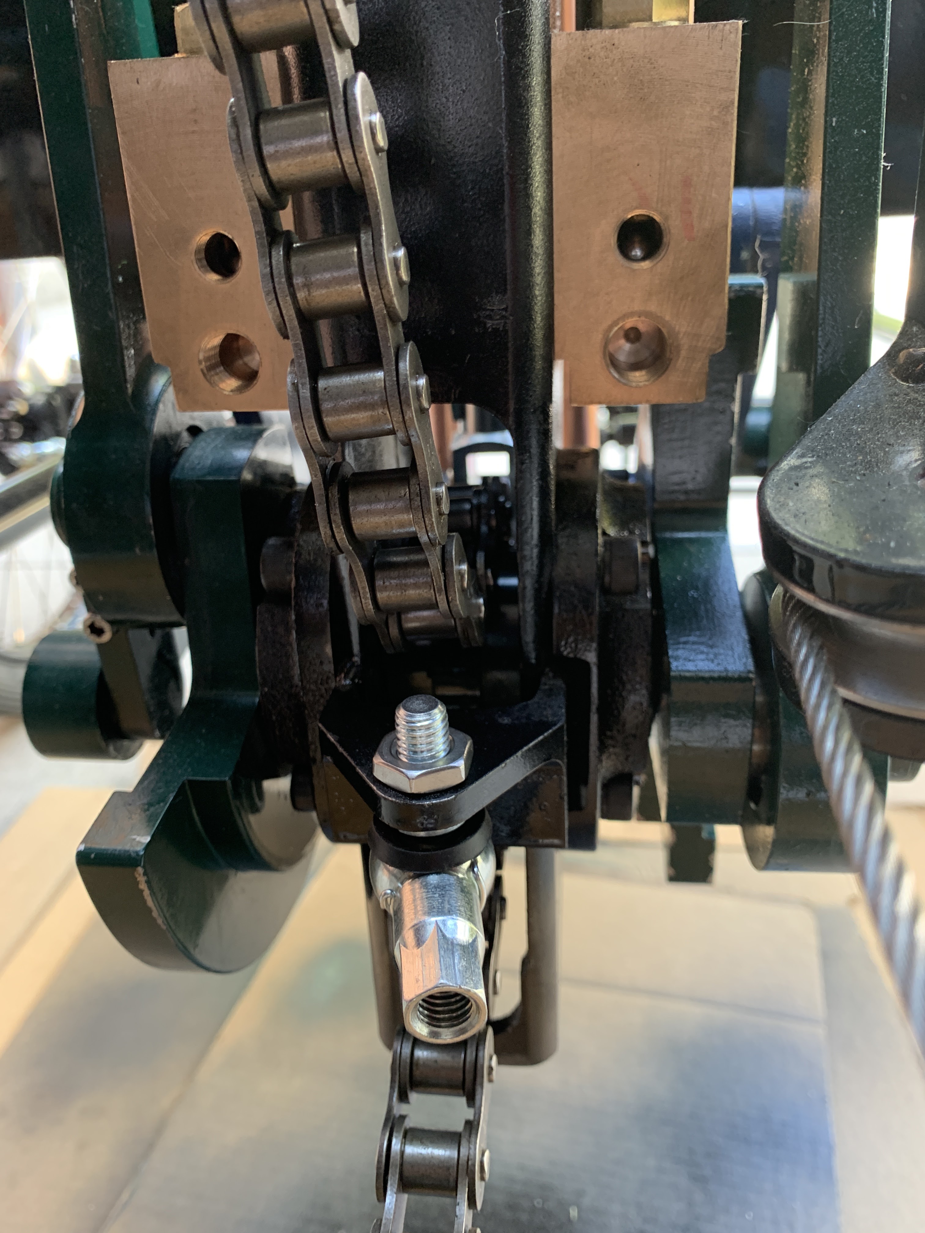
After grinding down the excess bolt length and pulling the chain just tight enough, The droop is gone and the chain will clear the bolt. 


So finally, the chain in place between the differential and the engine, checking the alignment.  If I need to remove it to install the boiler and burner system, I will be able to hook it back up without a lot of crawling under the car. 


Leaving it hooked up for now.  


Thanks for reading,


Regards,

Poppapope
Denver, CO USA


The Boilers are a-coming - soon?

 Boiler update - 

I heard from Steam Traction World that the boiler design has finally been approved and the boilers were in production.  It seems that since Brexit, there are now TWO agencies to make happy, one in the EU and one in the UK.  They each have similar requirements, but must be dealt with separately. 

Dean, the director of STW was kind enough to send me a picture of the boilers underway. 

Hopefully, now that the details are worked out, the remaining kits can get organized and packaged without further delay.  We have stalled waiting on the boilers with only piddling stuff to work on for the past year.  It will be good to back on track.  


Brake Light 

During tests of the electronic package I designed, I discovered that the switch I had configured on the brake pedal was not going to work.  The amount of movement required for switch contact was only about 1/8 inch.  I am concerned that the vibrations in normal travel will result in false indications.  

I found a more conventional brake switch that has a spring-loaded system where the contact is made after about 1/2 inch of travel.  

The original attempt: 


I removed that bracket and built a new one to hold the larger switch.  The switch and bracket both have a little bit of "springiness" to allow the play in the pedal.  


Playing with the Sight Glass Assembly

A part of Kit 18 was the Sight Glass Assembly.  This consisted of two very hefty metal parts, one brass - one stainless, a glass lens, gaskets and a sensor system for the water level.  

The hole in the back is for the sensor.


Steam Traction World had provided Black Oxide bolts, I replaced them with Stainless & Washers.


Water level sensing is done by using an IR (infrared) led and sensor.  The prism lens changes how the light refracts when immersed in water.  The change in levels is sent to the circuit box (in background) where it will open or close a relay (depending on the change) - if the relay is open, the flow of electricity to the burner relay is interrupted.  This circuit is in series with two other control points, the pressure switch and the burner enable switch (on the dashboard).  

The water level sensor control. - Three Off-the-Shelf parts in a small plastic box.

The end result is three places that need to be in agreement in order to fire the boiler.  I am also contemplating another level sensor, one that also had high and low points, in order to control the water bypass valve. 


However - all of this goes in AFTER the boiler. So we will just have to keep on working on the little pieces that will help it go all together. 


Thanks for reading,

Jim Pope
Denver, CO USA