What its all about

Poppapope's Steam Car

The Engine - Part 3a

Kit 13 (Mostly) 

Kit 13 has a lot of parts, primarily for the linkages on the engine.  These would encompass the main slide valve section and the Hackworth section.  The documentation says "modified Hackworth" - Since I am unfamiliar with "un-modified Hackworth" I can not tell what the differences are.  Typically slide valve engines have a method of changing the timing of the valve and thus the order of steam being introduced into the cylinder behind the piston.  

As I said in Engine - Part 2,  there are a number of inter-relationships between the various sections.  As a matter of fact, I wish that STW would have moved a couple of things around in the sequence.  Most notable is the Reversing Linkage Arm and Shaft.  If these had been moved to Part1, the builder would not have to disassemble the main cranks, counterweights (webs) and related arms in order to fit them in. 

IT WAS A MAJOR PITA TO HAVE TO GO BACK AND FIT THEM.

Back in Part 1, I knew that the bushings would need fitted, so I retrieved them from Part 3.  It is the linkage arm that threw me,  I needed to grind down both sides to get it to fit on the shaft, and rotate easily.

The Reversing Arms fit into place on the shaft and complete this section of the assembly.  More to come after the cylinders,  Steam Chests, and Slide Valves are fitted.  

Cleaning up a mistake.

I started playing around with the cylinders and pistons in Part 2. I had realized that I had gotten the connecting rods facing the "wrong way out" which might have ramifications in the clearances when adding the linkages.  So I took the time to fix this.  The gudgeon pin had to be extracted and the rod flipped over. Now the correct side is facing out.  This took me a while to figure out the sequence needed to accomplish.  I justified the time by saying to  myself that I needed to know how to service everything, so learning the disassembly process will be time well spent.  -  Yeah - Right.  Next time pay attention to the drawings. 


As long as I had things apart, I went back to the cylinder mounting plates. In his blog, Grier had cautioned about the cylinders working loose.  So I took this to heart and add some additional punches to the flat-head screws.   I was going to add thread-locker - but Grier said the heat degraded what he had used.  So I hope the "mechanical" connection will suffice.  


By now I have assembled and disassembled the pistons, rods, cylinders, connecting rods, crossheads, guides and everything in between.  Hopefully for the last time!  


So that sets it all up for the valves, steam chests, and timing linkages.  

More to come. 


Thanks for reading, 

Poppapope
Denver, CO USA


The Engine - Part 2

 Kits 11, 12, 13

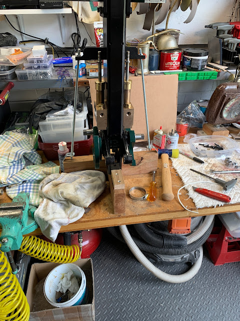
Now that the crankshaft and webs are in place, the engine can sit on the stand and be built up in place. I know that it will need to go into the chassis at some time, but at least the during the initial build and test, it can be on the bench. 

Kit 11 also contained the cylinders and base plates.  I painted the cylinders BRG and the plates black.  The flathead screws used to attach one to the other needed to be ground flat with the plate in order to sit on the post correctly.  Since you do not want the screws to work loose in any manner, I used a punch to dimple the edge of the screw head as well as RED Threadlocker.

So at this point we are done with Kit 11. 


Kit 12

Kit 12 is all about the pistons and pumps.    We have the pistons on the piston rods, crossheads, crosshead guides, connecting rods, covers, gland packing and dual water pumps to put together and fit into place. 

By now I have gotten in the habit of laying everything out and memorizing names in order to avoid the "what the hell is that thing" syndrome.  It is better to have a name in your head, even if you spell it wrong,  so you can look it up and check it's location on the drawings and in the text. 

So I spent a lot of time putting pieces in order, connecting and disconnecting,  and familiarizing myself with the order of assembly.  This is all so I get things right-side-up and not inside-out.  inserting the crosshead in the right direction helps when you are only holding things up with a fingernail while trying to get a bolt started.

Crossheads

The crossheads transfer the motion of the crank via the connecting rod to the piston.  The big end of the connecting rod travels in a circle with the little end going up and down.  The crosshead is confined to the crosshead guide and translates the movement to purely up and down.  The crosshead also has a connector that drives the water pump. 

The important part of all this is that there is a fairly close tolerance between the crosshead and the guide. The crosshead must move smoothly up and down and also survive slight rotational urges without binding. 

Another important thing is that the crossheads are cast iron and the piston rods are stainless.  Screwing one type of metal into another has been know to bind up and that would not be a good thing in this case.  It would very very hard to get a grip on the crosshead or the piston rod without something getting marred. 

To avoid this I re-tapped the crossheads to clean up the threads, using a little "Tap Magic" to lubricate. 


 Crosshead Guides

Due to the fact that the cylinders are rotated about 45 degrees off square and the cover bolt pattern is put on them identically during manufacturing, the guides are made to be RH/LH so that the crossheads and pump linkages all work correctly.  So until you can work with everything upside down, it is a good idea to id them as you go.  STW made this easy because they switched out manufacturing methods in the middle of my kits.  One guide is cast iron, one is steel.  I queried Lynn in support about this and was told that there was an issue with the foundry, in that they shut down, so there was a bit of a scramble to bring in another source, therefore, STW decided to change this part from CI to CRS. 

To tell you the truth, once cleaned up, edges rounded the same, and surface sanded/buffed, the application of paint pretty much negated the differences. 


Connecting Rods

Degreased,  painted,  bushes installed, bearings installed and all is ready to go.  The only real adjustments was to the "little end" where it slid into the crosshead. I changed the radius of the little end to flatten it out a bit. 


Pistons and Rods

The pistons were pre-installed on the rods and the retaining nuts were secured by additional punch-points in order to keep us builders from getting into trouble by having the pistons fall off in the middle of a run! 

The rods are actually a little too long (1-2 threads) and needed to be ground down in order to avoid interference with the little ends of the connecting rods. 

The piston rings were too tight in the grooves of the pistons.  I used s sheet of emery paper on a granite tile to take them down to a nice slip fit in the grooves. 

A couple of grooves in the Gudgeon Pin allows the grub screws to have something to bite into. 


Last but not least, fitting the piston to the bottom cover with gland packing in place. 


Water Pumps

There are two pumps in the system.  Each is driven by the appropriate crosshead.  You must just do the final assembly and adjust the little ball clearance.  This is done by moving the head of a bolt up and down.


The pumps mount to the side of the main post right above the crankshaft.  Watch your fingers - the edges are sharp.  After catching mine, I took a small flap wheel to them (the edges not the fingers!).


So  -   At this point I have the sub-assemblies built and fitted.  I am going to tweak some things like the gap in the piston rings and then read up on the next step in the process.  I assembled both sides and worked on the alignment of the crossheads once the pistons are in place.  Here is a final view before I take on Kit 13. 


Kit 13 has all the timing and reversing components, so before I lock down Kit 11 and 12, I need to make sure Kit 13 does not impact anything.  

So stand by,   

Thanks for reading.

PoppaPope
Denver, Colorado USA

The Engine - Part 1

Kits 11, 12, 13.

Now that the chassis and frame are complete,  I can begin to work on the engine.  STW ships the engine in three kits.    One would be smart to wait until all three come in.  This is to avoid having to disassemble parts from Part 1 when additional pieces show up in Part 3.

The engine is a dual cylinder, double acting, high pressure, 2 1/4 diameter 3" stroke, non-condensing with a modified Hackworth valve gear.   And it has lots of places to smash your fingertips. 

The first thing I did was to partially unpack the three kits just to get a feel for the scope of this part of the project.   

 
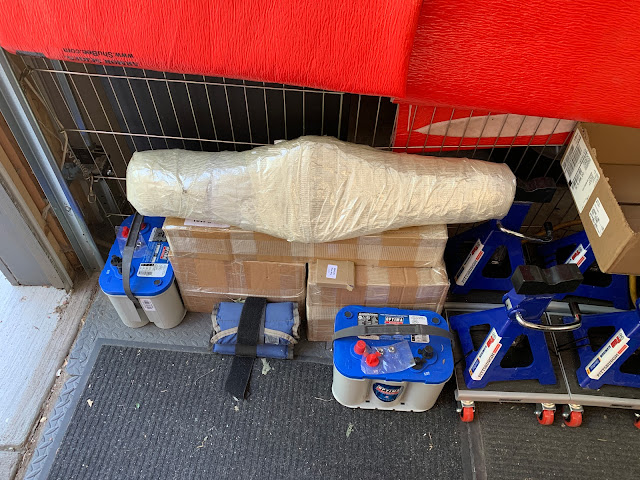
KITS 11, 12, & 13 - Still as received.  (Batteries not included) 

 
Partially unpacked. 

Lots of pieces, totaling over 100 lbs.  I can see where it will become uncomfortable to roll around and work on, not to mention just heavy.  I would be concerned with items getting out of position, bent, damaged, or just a total PIA.   

To that end, I recalled a picture from another build, where a stand was built to hold everything upright. 

I pulled some scrap 2x4 pieces together and added two brackets and pieces of all-thread with some nuts. 
That yielded a suitable stand, stable enough to rotate and work on all the way around. Initially, I had to fit the drive cog and crankshaft to the end of the center-tube first.  After reading Grier's blog I knew that some smoothing was necessary for the fit. So that and the painting came first, then the fitting of the cranks, followed by the mounting on the stand.   


Since the build instructions are organized by "Kit", I laid out the first one, looking to de-burr holes, select a paint scheme, and begin to fit parts to the main post. 


The Crank Webs, Shaft, and drive cog/gear were pre-assembled.  They did not want to come apart.  I happen to have a gear/pulley puller from my days 50 years ago as a teenage Volkswagon owner,  and it managed to pop the webs off the shaft.  I have not managed to get them back on (totally) again. Not with a mallet, a monster C Clamp, or vice.  The last 1/16 inch may come back to haunt me.  


Paint - What gets what.

Next I needed to finalize the paint scheme for the overall vehicle.  I have a copy of the history of the Locomobile from the Stanley Museum.  The author went into great detail, including the paint schemes. 
Obviously Black is a common base coat, then for the accent colors you will fine Red, Yellow, and Green. 

I am partial to green.  Hunter Green to be exact.  This is a little lighter than BRG (British Racing Green) although both seem to have various formulations and subtle shadings as to be all mixed up.  

I went looking and found that high-temp paints are of a couple of different types.  I settled on a brand called Dupli-Color that has Engine Paint w/ Ceramic.  (Ceramic what? I am not sure.)   They say that the paint will withstand temperatures up to 500 Degrees F.   The fact that it does not require heat treatment or long cure times was a bonus.  3 hours to handle, 24 to fully cure.  

Dupli-Color has a BRG and a Gloss Black that both look great.  They are enamels, which means they will paint over just about anything.   The paint goes on very smoothly, quick to build up, glass finish. I am very happy with it so far. 


It is at this point that having all three kits made things a little easier.  I had read in Grier's blog that about 1/2 thru the engine he had to do a little disassembly when he got to kit #3.  This was for the reversing control shaft and the associated bushes.   I dug into the kit and got the bushes out.  They pressed in quite easily.  As did the main crank bearings. 


To finish out this blog entry - I test fitted everything so far.  Everything rotated very nicely indeed. 


So - lets have a movie. 


That's all for this entry.   

More to come,
Thanks for reading. 

PoppaPope
Denver, Colorado USA


Kit 10 - Brakes - Pedals and Piping

Brakes - 
Not my strong suit.  I know how to use them and in general how they are supposed to work.  I have never had to maintain any.  I just know a "spongy" pedal is bad.  So this was an interesting couple of days.  
 

Pedals

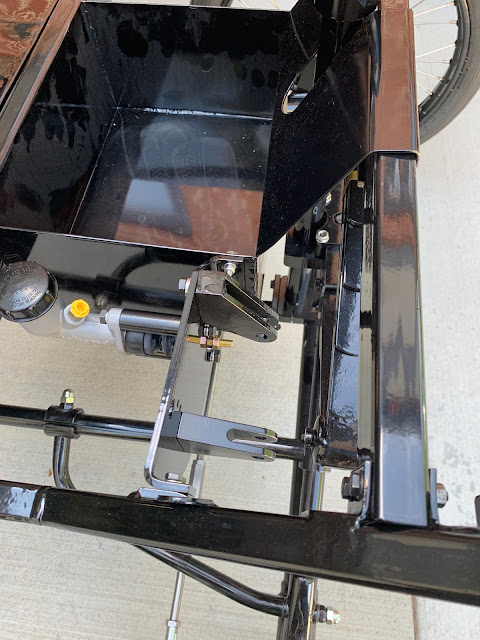
There are two pedals in the Lyka.  One to adjust the flow of steam, one to make you stop.  They mount to the "Pedal Plinth" provided with the frame.  It is a heavy duty piece of steel that bolts between the frame and the Battery Box.   Holes are pre-drilled, and mounting hardware provided.  I added washers and lock washers.  I also Loctited the bolts used for the brake cylinder mounting. 


After mounting the pedals, I wrapped the accelerator pedal to keep it from chipping paint as it will be awhile until it gets hooked up. 


Rigid Piping

Also in the kit are pre-made rigid pipes with flared connectors and nuts.  There are also 3-way units and also a supply of banjo and bulkhead connectors to make up the flexible pieces.  A bag of cable clamps round out the supplies. 

There are no detailed drawings of the overall brake system, but STW does provide a series of closeup pictures.  These provided enough information to get myself started. 

The first thing I did was to mount any hardware.  The 3-way connectors attached at the wall next to the master cylinder, at the front near the steering connection, and on the rear axle near the differential.  I dislike having connections rubbing against painted surfaces, so I made "stand-offs" using extra nuts.  This made sure my wrench would not mess up the finish, and on the rear axle housing, it made sure that the bolt would not impact the axle rotating in the housing. 


The pic above shows how much extra the bolt has.  Made me worried about impact.

The same connector location after the standoff installed.

The front connector.

The main connection at the Master Cylinder.  I am not sure all that will go into the "Battery Box' so I wanted to keep the "snags" to a minimum.  The pipe going "up" is the long feed to the rear. 

And just so no one can tell me I am not consistent - the clamps are also with stand offs especially on the rear axle. 

The Game's Afoot - 

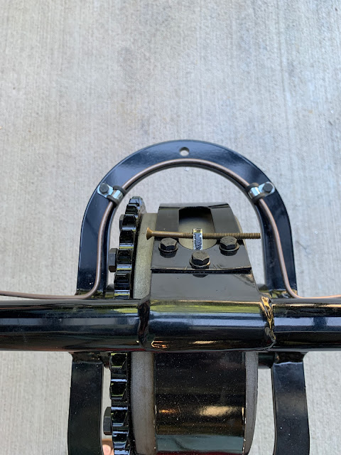
Last but not least is the routing of the rigid pipe around the differential.  Now you have to understand that part of the "game" is that STW does not always tell you what is to come.  So in the picture of the band that goes around the differential, they just show the pipe sitting there, bisecting the hole.  Then the instructions say to "drill a hole" for one of the pipe holders. 

OK, I can drill a hole to hold the pipe in place - but what is the other hole for?  Well - thanks to Grier,  I come to find that the hole is for the Chain Tension Adjuster.  If I had not paid attention to that, I would have a conflict -  Also - from Grier's Blog,  there was a comment that only 5 of the 6 pipe clamps were allocated by STW. That allowed me to maintain symmetry.  Something I like to do as often as possible.


 Flexible Lines and Connectors

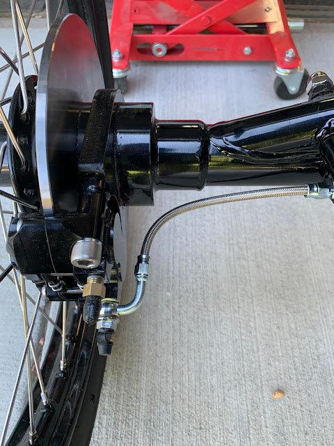
The "last mile" in the brake system are flex lines that tie things together and connect to the calipers at each wheel.  STW gives you "just enough" bulk cable to build the 6 flex lines you will need, one for each wheel and two for interconnections.  And I mean that - Just Enough - I had 1.5 inches left over.  So this is a case where you need to measure about a dozen times before you cut.


I used a dremel with a cut disc in order to avoid messing up the braid.


You push an "olive" under the braid.


Then finally tighten everything down.  


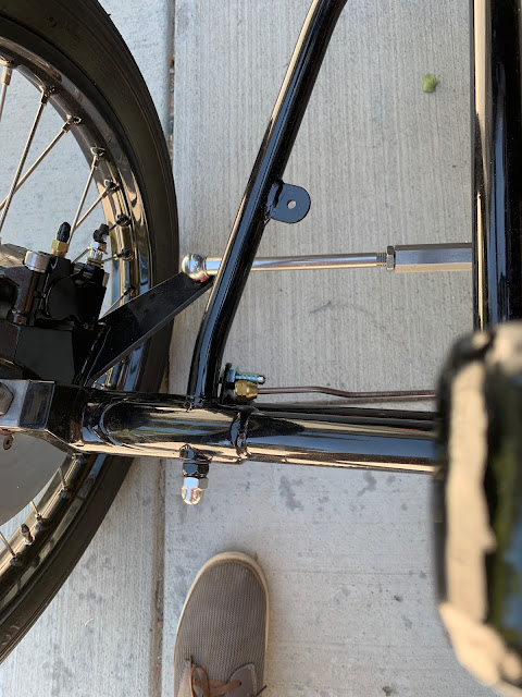
Finally, you need to verify that the flex lines are "just right" on the front wheels,  testing the full range of motion, checking to "too tight" or "too loose". 


On the rear wheels, you just don't want a constant rubbing. 


Brake Bleed Screws

In the pile of parts in Kit 10, there were 4 banjo connectors along with banjo bolts.  The banjo bolts had integrated bleed screws.  The instructions say to put the bolts in the UPPER hole in the calipers.  As provided by STW, there were not any other bleed screws.  So this did not make sense to me.   The bleed process would remove air up to the caliper, but nothing was going to "draw" the air off and fill the caliper with fluid.   As a matter of fact the instructions for the previous batch of Lykas said to put the bolt in the bottom, and that additional bleed screws would be forthcoming.  (Grier told me this did not happen.)  

So - I ordered 4 M10x1 Brass Bleed screws and decided to put those in the TOP port (removing the ball bearing) and using the banjo system in the bottom port.  Then I used thread sealer on the bleed port of the banjo units just to seal them up.   


When I get around to actually adding the fluid and bleeding the brakes, I will report the results of my efforts.  

Thanks for reading,

PoppaPope
Denver, Colorado USA