I got word yesterday that the powder coater, Colorado Powder Coating, had finished with the first two batches I sent them. The Chassis, Steering, and Differential (Kits 1, 2 & 3) and the Leaf Springs (Kit 6) all had parts that could be coated rather than painted by me. Those were now ready for pick up. The next pieces for coating are the Body Frame (Kit 8) and the Tanks (Kit 9).
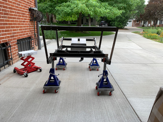
So, not being one to waste too much gas in these times, I only wanted to make one trip. I knew that there would be some preparation required, so I started to work on the frame, using the jack stands to keep it off the ground.
My previous post "A Penetrating Glimpse Into the Obvious" detailed the slight detour in life that took place. Here we will just focus on the actual assembly after the fog lifted and clarity resumed.
The Base Frame
I strapped the two side frames to the jack stands and started with the middle two cross members. This is because the slant of the ends of the members will determine the "tilt" of the frame sides. I had to drill a little bit of the bottom bracket of one of the sides that held the front-most mid beam in order to get the bolt in smoothly. Once the two mid-beams were in, the front cross beam and the rear one, a piece of angle iron that just sat on top, fit very well (minor cleanup on the front) and everything tightened up.
Top Frame
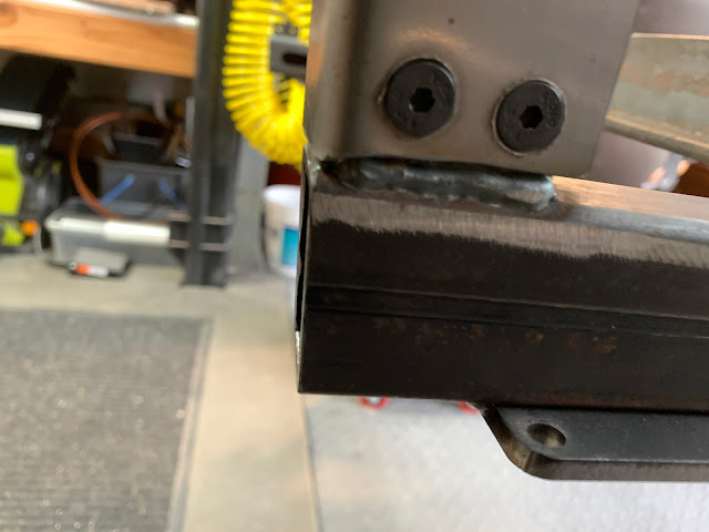
Once the base frame is completed, you need to build the top frame, linked by four vertical posts. There is a very sturdy plate welded to the base frame at each location. Due the angles involved, it is important that each post sit "flat" against each plate. The weld bead on the outside edge of each plate will interfere with this unless you grind away either a little of the bead, or "notch" the end of the post to fit. I do not like to remove nicely done welds, so I chose to notch the end of the posts. Used an Angle Grinder - my new favorite tool, and flap disc, working on each post until everything was stable. Some of the holes in the plates needed to be countersunk a little to accommodate the fact that the flat head bolts protruded thru the posts about 1mm and needed a little relieving. Following the hint in the notes, I left each post a little loose to allow for flexibility in the attachment of the upper level.
The top frame attaches to the four posts in an interesting series of interlocking flaps and tabs resulting in a nicely presented structural assembly. That is - once you figure out that the two small plates they give you are needed to attach the front pillars to the end of the side frames. With everything attached but slightly loose, you square-off the front posts with the base frame, and tighten everything up.
The final touches on the frame is the additional two heavy iron brackets in the rear (boiler supports).
The Battery Box
The Battery Box fits between the two front cross beams. It is made of heavy gauge steel, and just hooks over the beams. However, a little adjustment to the bend angles is needed to get things to lay flat.
This was a test fit - once the battery box dropped into place, the "Pedal Plinth" also squared up nicely.
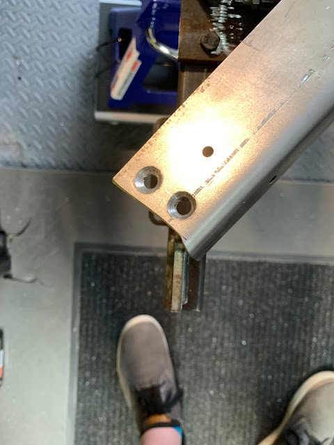
Here we see the "One-Footed Angle Adjuster" in action.
Once the "Angle of the Dangle" was corrected, everything dropped into place, including the Pedal Plinth (say that 10 times fast) that gets bolted between the side frame and the Battery Box. The batteries I will be using were tested to confirm the fit, and all is well.
Now - I just needed to take it all apart and get it to the Powder Coater tomorrow. I will have the original batches from them and can get started in the correct order.
NEXT - Kit 1 - Fully Painted Assembly.
Thanks for reading.


No comments:
Post a Comment
Thank you for posting your thoughts on my build.