What its all about

Poppapope's Steam Car

What a strange, strange trip it's been!

The journey so far - a recap. 

Here is a picture of my girl as she sits in my garage, today, May 24 2025, almost 3 years to the day from when I first fondled her frame.


Where am I now?  Well I have received about all that I will be able to get from STW.   I did some electrical engineering for them last fall when Dean was still in charge, and that has allowed me access to some details that might otherwise not be in the public domain.  Also this relationship has allowed me to receive my boiler and about 80% of the remaining parts well in advance of other Lyka builders.  (Sorry, not sorry).  My boiler has been fully tested but it was not officially blessed by the BES.  Since the USA does not give a rats ass about the BES, and there are no anal retentive inspectors looking over my shoulder,  I asked to get my boiler NOW.   STW obliged, and also picked as many of the available parts for kits 20, 21, & 22.   What I was missing were some commercial items, like the pressure switch, safety blow-off valve, pressure gauge, the hand pump and a bunch of the copper pipes.  I sourced all of the commercial items - mostly from McMaster Carr, Zoro, Steam Fittings UK, John Rex Engineering and Amazon.  The remaining copper tubing I bought in bulk and learned how to do a "double flare".  

For my fellow Lyka builders, I think there are about 9 of you,  I will recap some of the things I encountered as I have gone thru the remaining process.  A lot of this is covered in the individual posts so you can look there for more details.   You should also study Grier's blog from the last build (2016). There is a link over in the right side column.   

Since most of you are still waiting the boiler, I am assuming that you also are either waiting for or holding on: 
Kit 15/16 Boiler
Kits 17a/b (flame shield, smoke hood, cladding, 
Kit 19 - Some pipework, valves, inverter.
Kit 20 - Burner
Kit 21 - More pipes
Kit 22 - More (last of) pipes
 
During the last year you probably got:
Kit 18 - Wire loom, control box, regulator, chain. - Water Sensor (more on this).
Kit 23 - Body panels
Kit 24 - Seat
Kit 25 - Rest of Seat. 
These 4 kits may be sitting in your "pile" at STW, in your garage waiting for action, or like mine - built, finished,  enhanced and then stored until the rest comes in.

My build status: 
I am waiting of a DHL shipment with 3 valve bodies from Kit 19 and a new inverter.   Then I will be ready to begin pressure testing using water and air.  Following that will be the burner install, adjustments and further testing.   Then comes the first drive down the road.  
 
Look to the next episodes for all of this. 

If you have been following my posts to date, you know my background.  While I am new to this size of steam vehicle, I am not inexperienced in steam in general, and I have build a lot of stuff over my 73 years on this planet.  What I want to do with this post is catch you up on details covering the second 1/2 of the build. 

General Observations - covering all kits.

The Lyka project lost it's champion after Steve died.  Dean carried on with the help of Ian,  but Ian retired in 2023.  Since then Dean was pretty much doing what he could, but just did not live and breathe the Lyka.  All the other engine products of STW are very well known to the staff,  but not the Lyka.  However, Dean was committed to all of us builders and I do not think our "investment" was ever at risk, even during/after Covid.   What has further complicated things is that STW shuffled the kit contents a bit.   So what was done in the 2016 build was not done in quite the same order in the 2022 build.  Some of us like to "read ahead" and luckily Grier posted all the instructions from the 2016 build cycle.   We just have to adjust for the shifting that has gone on.   
 
If you have gotten thru Kit 14 (the engine) and maybe worked on the body panels, you should go over to Grier's blog and DOWNLOAD INSTRUCTIONS FOR KITS 15-23 (Boiler thru the last of the pipes) Note that Kit 23 (2016) included both body panels and pipework.   Why do this - because STW has probably left out some details in the current instructions.   It is possible that they may have corrected the information, but why take a chance? 
 
Lastly, a word of advice, DO NOT Mount the sheet metal (Flame/Heat shield - bottom, Smoke Hood - top, Cladding/Smartwool) and Boiler UNTIL you have worked out all pipe runs.  While the instructions allude to this, let me tell you that getting everything laid out, even if you take it off for a bit, is a LOT easier with out the boiler and the rest of the stuff in the middle.  

Kit by Kit

Kit 15/16 boiler - It is a lump.   A hernia just waiting to happen.   Get a small "trolley" or "dolly" and use that for moving it around.  But get some blocks of wood so you do not mess up the fittings you will insert into the bottom.  

KIT17a/17b Heat shield, smoke hood, cladding - also has the fittings for the boiler mentioned above. 
If your instructions do not have pages with a bunch of pictures (not ISOs) then download the instructions for Kit 18(2016) from Grier's blog and use those.    
My Kit:  
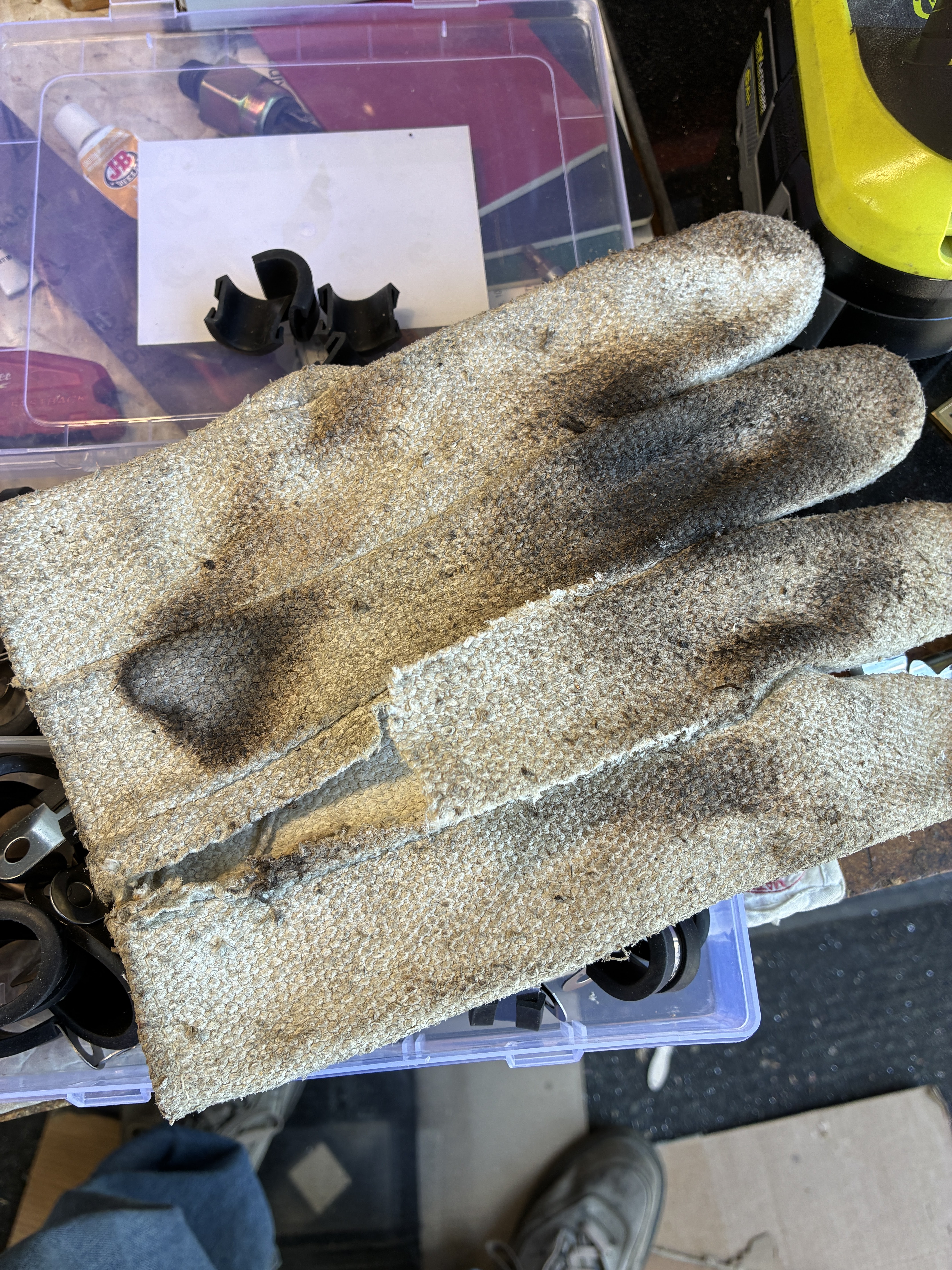
The bottom inside heat shield did not have the holes drilled for the standoffs. The plate for mounting the burner,  the inner/outer shield did not quite line up.  So I had to use longer screws and pull things into line.  Some screws needed to be left out all together, and I just made sure that the smart wool was well placed.
 
SMARTWOOL is really a bitch to handle, first time my hands itched for a day.  Wear gloves.
 
When you pre-stage the boiler -  note that the ISOs and pics may not agree on the bottom right side blow-off connections - ISOs have a 2" nipple, Pics have two Ells - go with the pics- read the text.  ALL CONNECTIONS - you will never see these again when they are assembled. STW has the habit of "tapping deep". so on all the connections to the boiler inside the shields, I used X-Pando. it is a steamseal on steroids.   AND CRANK IT DOWN - ONE MORE REVOLUTION THEN YOU THINK YOU CAN DO!!!  
 
On the top connections,  after doing a dry-fit,  and marking where the pieces need to go along the side of the boiler in order fit smoke hood, then mount everything BUT the center (main) output.   See my post about the boiler.  Once you install the boiler - you can put in the main outlet - but look for the Ell at edge of the boiler, you will need to heavily modify the upper/outer smoke hood to get that to fit. 
 
AT THIS POINT STORE THE HEAT SHIELD/BOILER/CLADDING. 
 
KIT18 - The water sensor.  In the original Kit 18 there was a water level sensor that included a modification of the back 1/2 of the reflex glass.  Ian (retired) had created a method to watch the water and turn off the burner if it dropped too low.   His design used a really nice optical unit that transmitted light (ir) thru the water and told a relay system in a small box that all was well.  If the water level dropped, then the relay opened and the burner was cut off.  The issue is that the sensor is plastic.  if you blowdown thru the reflex glass,  you melt it.
 
Dean commissioned me to expand on Ian's idea and create a sensor that would do the level determination electronically.  There should be a second sensor kit somewhere in your shipment.  I wrote an extensive manual to go with it.  RTFM.  If you do not find it, get with Production@ to request a kit be sent out.  
Read my previous posting to see about the mounting of the box.  I would wait until you finish the pipes to do so.
 
KIT19 - Drain down (blow off) valves, cylinder drains.   
Make sure you actually have the valve bodies.  My kit was marked complete, but the bodies were missing. If you have been sitting on the kit for a while, and you are missing the bodies, email Production@ rather than admin@ since Rosemary will just forward your issue anyway. 
 
Install these up to the point where you would hook them to the boiler.  See my posts about the steam chests.  

KIT20 (Burner) - Very straight forward, although you can not do anything until the shield is in place.  
You can drill the holes for the fuel filter bracket and make sure the copper tubing is run correctly.  However, you will need to hold off on the actual filter until the boiler and the rest is in place. 

KITS21 and 22 - all the rest, water pump feedwater piping, steam outlet, regulator, pressure switch, etc. 
This is the hard part -  WAIT UNTIL YOU HAVE BOTH KITS.  That way you can be sure you have everything and can stage it first.  
 
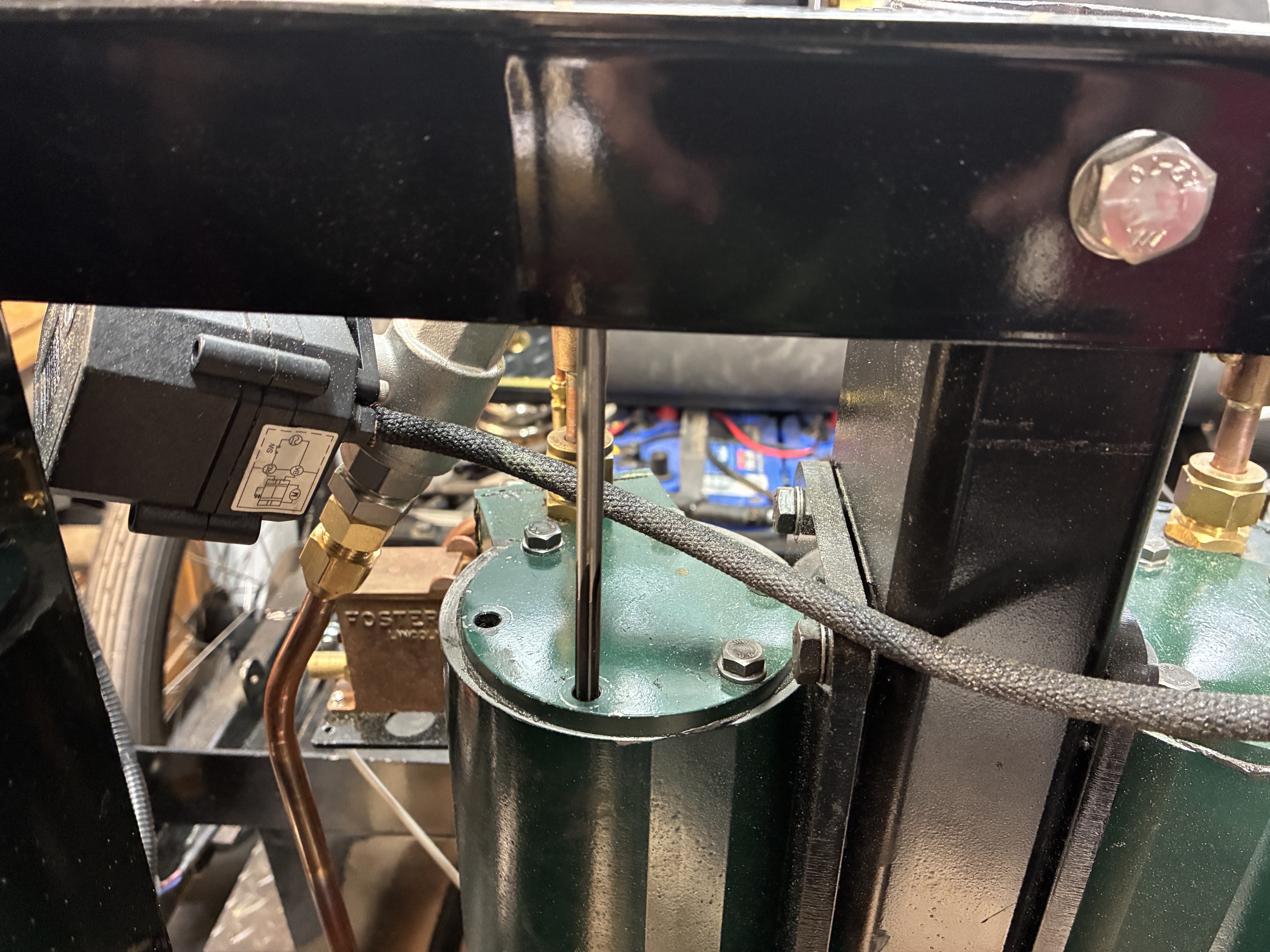
I would suggest that you put the fittings on the water tanks,  mount the tanks, do all the hookups where you can actually get to the piping as much as you can do. Then disconnect the flare connections at the tanks and pull the tanks - putting them aside for now. Leave the rest of the pipes in place, they will help hold up the heat shield later.  Build the feedwater system including the hand pump and it's connections. 
 
Run the small tubing for the pressure gauge/switch run and insulate any connection s you do not want to heat-up.  When you have done as much as you can do, stage the steam outlet connections.  

INSTALLING THE HEAT SHIELD AND BOILER
Contrary to the written instructions, insert the flame/heat shield FIRST.  Put a piece of cardboard on top of all the pipes you have already installed.  I used a floor jack to hold the shield up and engaged against the three support tabs.   I had to cut a little of the shield at one of the notches in order get it to fit.  Then you can lower the boiler into place and make sure to engage the two.  Keep the jack in place and insert the stays.   Remember that the stays in the rear positions need two nuts, one for the bracket, and one for the shield.  The front stay may be too long.   Cut it down to a more usable length.   I had to use multiple extensions and come up from underneath with a deep socket in order to tighten it up.  
 
Check out the previous posts for additional details.
 
 
In conclusion:
 
This series of Lyka kits may be the last for a while.  STW is in a state of transition mixed with confusion.  Dean was pushed out by his "partners" and it is up to the remaining production and office staff to make everything work.   The people I have been working with are trying very hard to fulfill all of the kits for the various models they have been producing.  I applaud their diligence.   

I have a few more things to do before I start pressure testing.  
More to come . . . 


Thanks for reading.
 
Jim Pope
Denver, CO USA 

Oh, and In goes the Boiler

First - Dropping in the Boiler

At long last.   The milestone I have put in my head for the last 2 years is placing the boiler in the chassis.  It became reality last weekend.   I have previously shown the preparation of the boiler piping connections.  The last connection, the main outlet, needed to wait as I used the hole to mount a T made of pipe in order to support the boiler from my chain winch. 


It took some help from a hammer and a little prying from a screwdriver but we got the flame shield in place and held up by the rear support while we wrap the smartwool and position the stays.  The front stay took a bit to get tight, I had to find a very long extension and come up from underneath. 


Then it was time to fit the smoke hood (the top).   This fit pretty nicely,  I had to enlarge the opening for the main outlet.  It has a very heavy-duty elbow. 


When I went to fit the metal cladding around the insulated boiler, I found that STW made an error in measurement.  There are metal tabs welded around the inside of the cladding.  The tabs are supposed to hold the cladding away from the walls of the boiler so it does not smash the smartwool blanket.  The problem is that the upper row was placed where it would hit the smokehood, rather than the portion below it.   I took my trusty angle grinder and took all of them off.  The cladding fit just fine without them and the brass banding holds it all together. 


Once the boiler was settled, it was time to assemble all the attached pipework.  First was the main outlet. The larger pipe feeds the regulator (throttle) and the safety pressure relief valve.  


I found that the whole "stage it first" concept really works here.  There are a few "critical measurements" in the assembly. Most notable is the location of the flare connection on the regulator in relation to the pipeing going to the inlet manifold.  Secondly, the angle of the bottom elbow that feeds the safety valve has some leeway but needs to point in a good direction. 

I found I needed to build the vertical section first.  In order to do that I had to start with the upper elbow, it needed to rotate so the T in the middle and the elbow at the bottom could rotate.   I made up a batch of X-Pando, which is a more robust form of steam sealer.   Applying it to all the joints in the vertical stack, I go everything situated and cranked down.  I temporarily (no goop) put in the regulator and safety valve in order to position things.  Then I let the whole thing sit overnight so the X-Pando could set up.  

During this time I found that my super-duper water level sensor kit box was mounted a little too high and needed to drop an inch or so.  There is a bracket attached to the end of the regulator that supports the pedal-cable linkage.   This would be rubbing against the top of the box, so I dropped in 1/12 inches.   

Easy to do because it was mounted on a plate rather than the side body panel.   I could then mount and trim the supporting brackets. 


Another set of crucial connections are the inlet to the check valve for the feedwater system and the oulet for the pressure switch and the gauge. 


Going back in time a bit, I had run the pressure gauge/switch piping before I put in the boiler.   I made some decisions in that I decided to use 1/4" copper for the pressure circuit as well as the fuel pipes just to make thing standard.  The pipe for the switch travels across the underside of the main girder then down to a T. From the T it goes up to the pressure switch and also continues across to the floor under the dash to the pressure gauge.  

To keep the heat from the tubing melting stuff as it went along, I used some cable clamps with the rubber removed and replaced with some heat-proof fabric cut from an ancient welding glove.   Then I added some additional ceramic heat wrap to avoid issues in the area of the circuit box. 

Then I ran the tube forward to the front floor area, bringing the pipe up from under and connecting to the gauge.  A little later, I added additional wrap in this area to afford some some more insulation. 

About 2 years ago I had a 4" Locomobile Repop Gauge built for me in black and brass to match everything else. 


The pressure switch is mounted on a custom bracket.  I was shorted the model originally in the kits, so I purchased a comparable unit and made the mount.  I added it to the plate I used for the water sensor box, and positioned it so I can adjust the setting from the front of the unit without removing the top body panel.  The sensor is adjustable from 75 to 300 psi.


I am waiting on the two blow down valve bodies that were supposed to be in Kit 19.   They are currently in a DHL shipment in New York, Should be here in a couple of days.  Then I can proceed to pressure test and get some water in the boiler that will enable me to test the burner without scorching it. 


I will continue with the burner install and the pressure testing after the next installment. 

I am going to recap the journey so far. 


Thanks for reading,

Jim Pope
Denver, CO USA

SubSystems Part 2

The Oiler System

The car needs to be oiled,  both in the cylinders and steam chests as well as the other moving parts.  

There are three ways to get oil where it needs to go.  

First is manually with an oil can, a squirt down in the guts of the engine, most of the bushes are oil impregnated, so a little to replenish is all that is needed in most of the joints.  

Second is the mechanical lubricators that are driven by a linkage off the slide valve rods.  The mechanical units have a ratchet system that produce a squirt of Steam Cylinder Oil about every 4th or 5th stroke.  The small squirts are introduced to the cylinders via small pipe with a check valve that keeps any backflow in check. 

Finally is a reservoir of oil that drips via small pipes onto the cross-head guides and the slide valve push rods.  

Mechanical Lubrication as provided by STW consists of two units that are mounted on small shelves attached to the face of the valve chests.   The units supplied by STW were missing from my shipment.  They are usually sourced from another company.  I have been following other builders of both series of Lyka's and comments have been made that the pumping method in the STW provided units was prone to slipping and early wear.   Since I did not receive the STW units anyway, I opted to pick up two Foster units.  To tell you the truth, I do not know where the term "Foster" originated.   The Fosters appear to be used lot on Traction Engines.  I see different sizes, referred to by the scale of the engine.   2", 4",  6" scale.   I went by the physical size and selected a 4" scale.   They fit on the shelves with some additional drilling for the mounting holes.


The orientation of the oilers needed to be setup so the ratcheting arms are on the "outside" where they can move up and down. 

After mounting the units,  I made two outlet pipes to run from the output port to the check valve attached to the inlet port on the main steam pipe.   Then I adjusted the linkages to the slide valve push rods to accommodate the change in position.


Drip Lubrication is accomplished using a reservoir that is attached to a manifold, sending the oil via tubing to the desired location.   In our case, we want some drips on each side of the cross-heads and also on the slides for the steam valves.    

To begin, I got a Leukenheimer Oiler off eBay.  Adding to that a 1x3 manifold, some compression fittings and 1/8" copper tubing.  I cut out a piece of aluminum bar to fit the top of the left cylinder.   Drilled holes to match up with bolt pattern and used two to secure the plate after painting it with matching engine paint. 


I put a dab of Steamseal on three bolt heads.

The marks gave me a drilling location.

I decided to only use the two back bolts.

Then to locate the oiler position.


Painted and in place.


A Momentary Lapse of Reason

Well, I fucked up.   During the process of attaching and detaching the back bolt on the oiler bracket, I over-torqued the bolt, and felt a "snap".   Stripped the threads.  ARRGGHHH!   

So what to do, and how to do it.   

It is kinda tight quarters in there.

The thought process: 
The bolts are 6x1mm.   
I can either tap to a larger size or insert a Heli-Coil thread replacement.  
The next size up is 7x1mm,  The tap for the Heli-Coil is also 7x1mm.  
So I tapped for 7x1mm and found some bolts (Amazon) which I cut down to size.  

The hard part was getting to the hole.  I have some "aircraft" (long) drills, but those did not give clearance for my drill.  The tap hole for 7x1mm is 6mm.  So all I needed to do was to clean out the remainder of the threads.  I used a combination of drills, twirled in my fingers, and reamers to smooth out the walls of the hole.  Then I used a tapered tap, followed by a bottom tap, with puffs of air to clean in between.   The taps I held in a socket with an extender to form a hand tap.  Tap Magic also was a great help.

If this had not been an existing hole, the process would have been much harder.  


No room to get at the tap handle.


So a socket driver as an extension worked great.


I guess it is a good thing I have most taps known-to-man.


Finishing up the Oiler System. 

Once I had the oiler and manifold mounted, I worked on the distribution.  I am using 1/8" copper tubing.  I picked up a number of fittings to go with.   The key fitting is the 1/4x40 cone&nut union.  I used these at the 4 endpoints for the cross-head positions.  First I determined the top position of the head during travel, and drilled a hole above that point on each side.  Then I tapped and inserted the fittings.  I add a "Tee" fitting to split each side.    


For the slide valve rods, I made the end pieces finish up flush with the rods.  Later I used a large drop of JBWeld to secure the tubes from vibration.


A final look at the finished Oiler System.


That finishes up the oiler.   I will get into the Burner system and the remainder of the Steam distribution to the pressure switch and gauge in the next posts. 


Thanks for reading,
Jim Pope
Denver, CO USA