
The Oiler System
The car needs to be oiled, both in the cylinders and steam chests as well as the other moving parts.
There are three ways to get oil where it needs to go.
First is manually with an oil can, a squirt down in the guts of the engine, most of the bushes are oil impregnated, so a little to replenish is all that is needed in most of the joints.
Second is the mechanical lubricators that are driven by a linkage off the slide valve rods. The mechanical units have a ratchet system that produce a squirt of Steam Cylinder Oil about every 4th or 5th stroke. The small squirts are introduced to the cylinders via small pipe with a check valve that keeps any backflow in check.
Finally is a reservoir of oil that drips via small pipes onto the cross-head guides and the slide valve push rods.
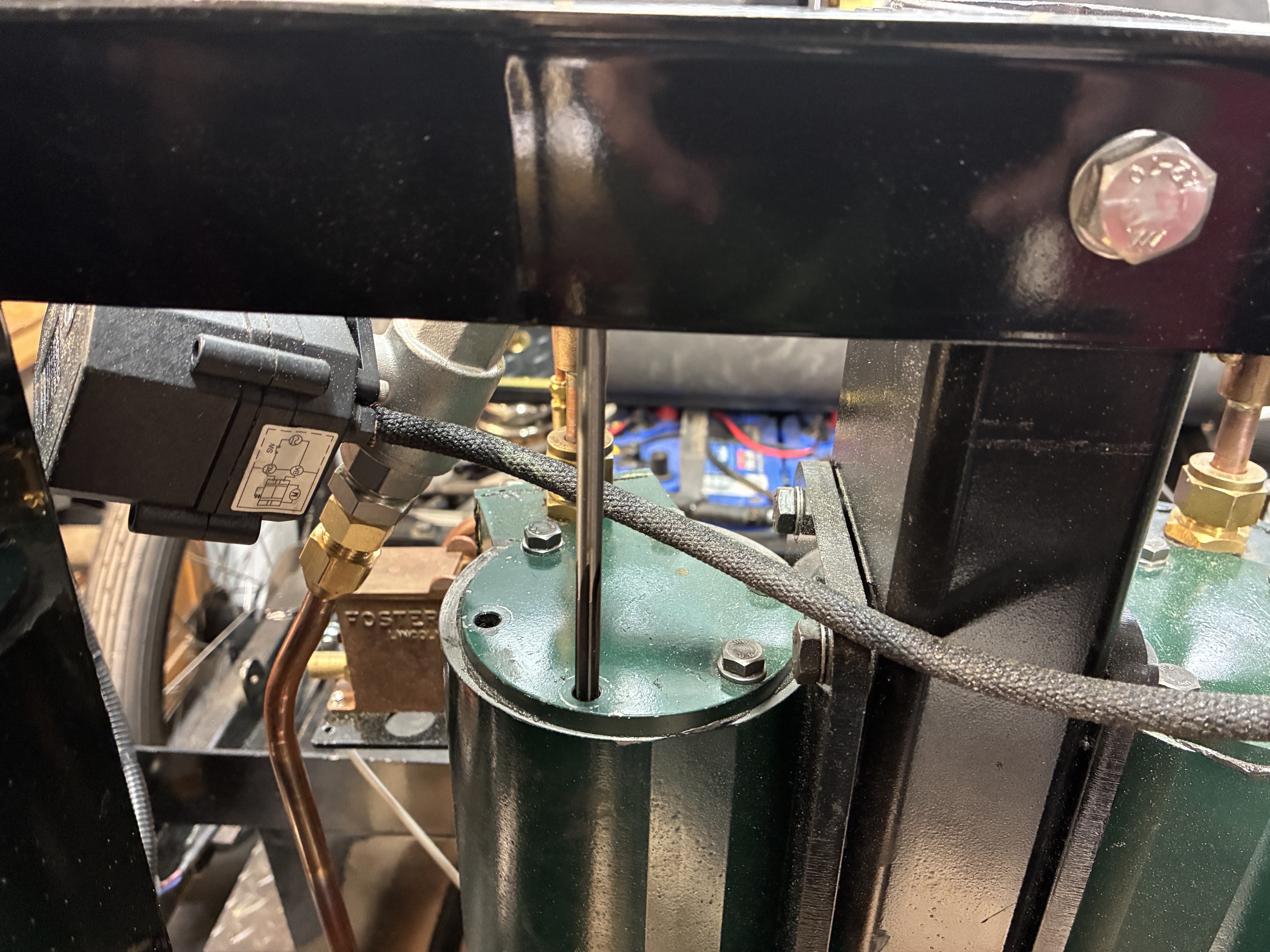
Mechanical Lubrication as provided by STW consists of two units that are mounted on small shelves attached to the face of the valve chests. The units supplied by STW were missing from my shipment. They are usually sourced from another company. I have been following other builders of both series of Lyka's and comments have been made that the pumping method in the STW provided units was prone to slipping and early wear. Since I did not receive the STW units anyway, I opted to pick up two Foster units. To tell you the truth, I do not know where the term "Foster" originated. The Fosters appear to be used lot on Traction Engines. I see different sizes, referred to by the scale of the engine. 2", 4", 6" scale. I went by the physical size and selected a 4" scale. They fit on the shelves with some additional drilling for the mounting holes.

The orientation of the oilers needed to be setup so the ratcheting arms are on the "outside" where they can move up and down.
After mounting the units, I made two outlet pipes to run from the output port to the check valve attached to the inlet port on the main steam pipe. Then I adjusted the linkages to the slide valve push rods to accommodate the change in position.


Drip Lubrication is accomplished using a reservoir that is attached to a manifold, sending the oil via tubing to the desired location. In our case, we want some drips on each side of the cross-heads and also on the slides for the steam valves.
To begin, I got a Leukenheimer Oiler off eBay. Adding to that a 1x3 manifold, some compression fittings and 1/8" copper tubing. I cut out a piece of aluminum bar to fit the top of the left cylinder. Drilled holes to match up with bolt pattern and used two to secure the plate after painting it with matching engine paint.


I put a dab of Steamseal on three bolt heads.

The marks gave me a drilling location.

I decided to only use the two back bolts.

Then to locate the oiler position.


Painted and in place.

A Momentary Lapse of Reason
Well, I fucked up. During the process of attaching and detaching the back bolt on the oiler bracket, I over-torqued the bolt, and felt a "snap". Stripped the threads. ARRGGHHH!
So what to do, and how to do it.


So a socket driver as an extension worked great.


Finishing up the Oiler System.
Once I had the oiler and manifold mounted, I worked on the distribution. I am using 1/8" copper tubing. I picked up a number of fittings to go with. The key fitting is the 1/4x40 cone&nut union. I used these at the 4 endpoints for the cross-head positions. First I determined the top position of the head during travel, and drilled a hole above that point on each side. Then I tapped and inserted the fittings. I add a "Tee" fitting to split each side.


For the slide valve rods, I made the end pieces finish up flush with the rods. Later I used a large drop of JBWeld to secure the tubes from vibration.

A final look at the finished Oiler System.

That finishes up the oiler. I will get into the Burner system and the remainder of the Steam distribution to the pressure switch and gauge in the next posts.
No comments:
Post a Comment
Thank you for posting your thoughts on my build.