
First - Dropping in the Boiler
At long last. The milestone I have put in my head for the last 2 years is placing the boiler in the chassis. It became reality last weekend. I have previously shown the preparation of the boiler piping connections. The last connection, the main outlet, needed to wait as I used the hole to mount a T made of pipe in order to support the boiler from my chain winch.


Then it was time to fit the smoke hood (the top). This fit pretty nicely, I had to enlarge the opening for the main outlet. It has a very heavy-duty elbow.


When I went to fit the metal cladding around the insulated boiler, I found that STW made an error in measurement. There are metal tabs welded around the inside of the cladding. The tabs are supposed to hold the cladding away from the walls of the boiler so it does not smash the smartwool blanket. The problem is that the upper row was placed where it would hit the smokehood, rather than the portion below it. I took my trusty angle grinder and took all of them off. The cladding fit just fine without them and the brass banding holds it all together.


Once the boiler was settled, it was time to assemble all the attached pipework. First was the main outlet. The larger pipe feeds the regulator (throttle) and the safety pressure relief valve.


I found that the whole "stage it first" concept really works here. There are a few "critical measurements" in the assembly. Most notable is the location of the flare connection on the regulator in relation to the pipeing going to the inlet manifold. Secondly, the angle of the bottom elbow that feeds the safety valve has some leeway but needs to point in a good direction.
I found I needed to build the vertical section first. In order to do that I had to start with the upper elbow, it needed to rotate so the T in the middle and the elbow at the bottom could rotate. I made up a batch of X-Pando, which is a more robust form of steam sealer. Applying it to all the joints in the vertical stack, I go everything situated and cranked down. I temporarily (no goop) put in the regulator and safety valve in order to position things. Then I let the whole thing sit overnight so the X-Pando could set up.
During this time I found that my super-duper water level sensor kit box was mounted a little too high and needed to drop an inch or so. There is a bracket attached to the end of the regulator that supports the pedal-cable linkage. This would be rubbing against the top of the box, so I dropped in 1/12 inches.
Easy to do because it was mounted on a plate rather than the side body panel. I could then mount and trim the supporting brackets.


Another set of crucial connections are the inlet to the check valve for the feedwater system and the oulet for the pressure switch and the gauge.

Going back in time a bit, I had run the pressure gauge/switch piping before I put in the boiler. I made some decisions in that I decided to use 1/4" copper for the pressure circuit as well as the fuel pipes just to make thing standard. The pipe for the switch travels across the underside of the main girder then down to a T. From the T it goes up to the pressure switch and also continues across to the floor under the dash to the pressure gauge.
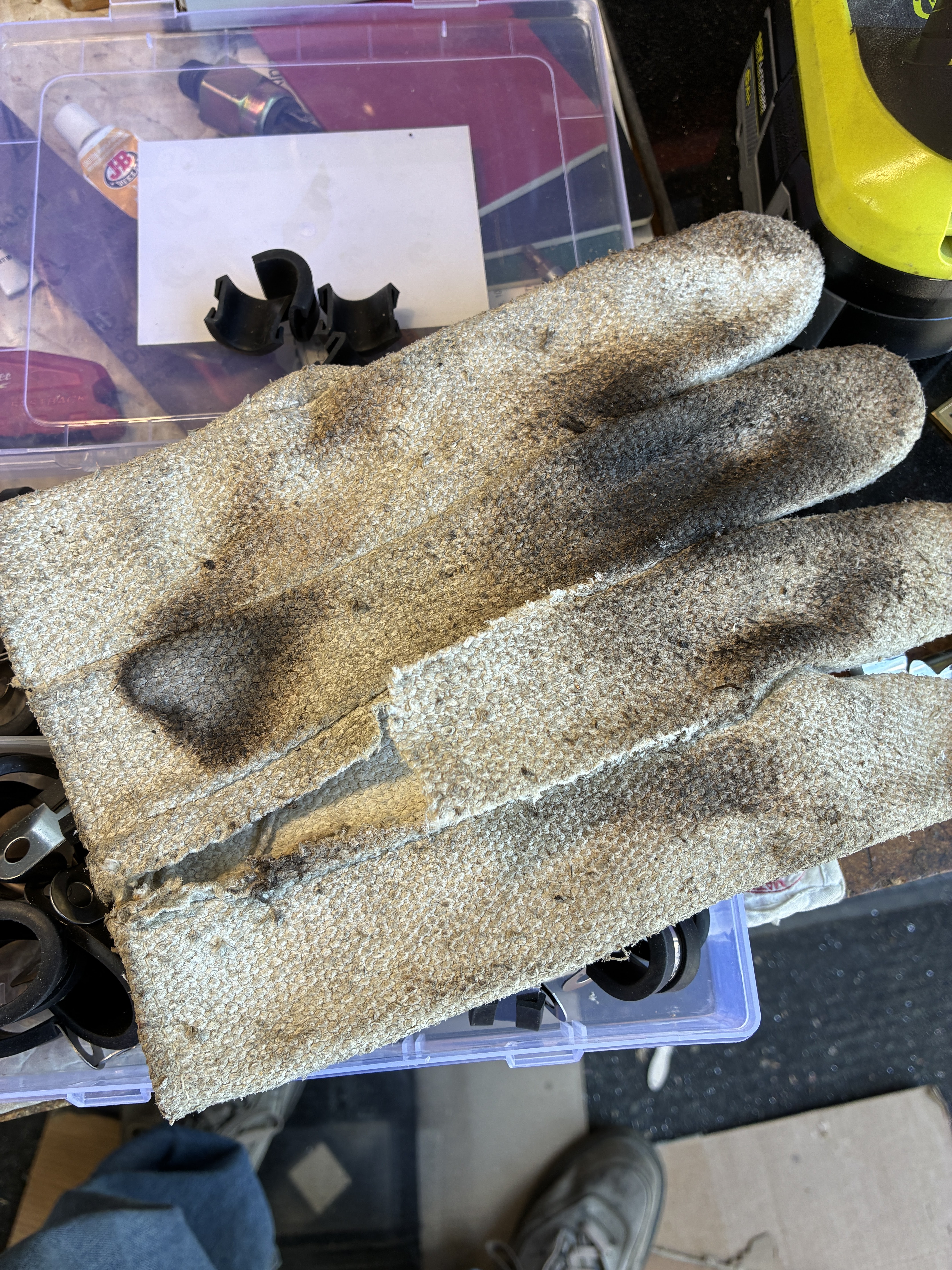
To keep the heat from the tubing melting stuff as it went along, I used some cable clamps with the rubber removed and replaced with some heat-proof fabric cut from an ancient welding glove. Then I added some additional ceramic heat wrap to avoid issues in the area of the circuit box.
Then I ran the tube forward to the front floor area, bringing the pipe up from under and connecting to the gauge. A little later, I added additional wrap in this area to afford some some more insulation.
About 2 years ago I had a 4" Locomobile Repop Gauge built for me in black and brass to match everything else.


The pressure switch is mounted on a custom bracket. I was shorted the model originally in the kits, so I purchased a comparable unit and made the mount. I added it to the plate I used for the water sensor box, and positioned it so I can adjust the setting from the front of the unit without removing the top body panel. The sensor is adjustable from 75 to 300 psi.


I am waiting on the two blow down valve bodies that were supposed to be in Kit 19. They are currently in a DHL shipment in New York, Should be here in a couple of days. Then I can proceed to pressure test and get some water in the boiler that will enable me to test the burner without scorching it.
I will continue with the burner install and the pressure testing after the next installment.
I am going to recap the journey so far.
Thanks for reading,
No comments:
Post a Comment
Thank you for posting your thoughts on my build.