
Trying not to be an asshole about delay after delay.
Excuse me while I wax philosophical for a moment. Here we are - two years along. The car is only about half built, and during the wait for the boiler I have managed to spend a couple of hundred dollars on things I thought I might want to put on the buggy. The old adage of the idle hands I guess.
I am extremely frustrated by the lack of "courtesy communication" on my kit progress. I send an email, and no one answers, not even with a "got it". I have taken to waiting a couple of days and re-sending the same email with - 2nd Try added to the subject. If that does not work, I go again with 3 Try. Usually I will get something back. But - if there is a question on the return topic, we start all over.
I refuse to believe that somewhere at STW there is not a large white-board with a master schedule. No production floor can operate without one. So - Why not communicate the plans to us folks waiting for the pieces? From what I can find out, my pile has almost everything but the boiler and the burner. The burner is on order from Italy, The boiler is still being "tubed". Now, I have never tubed a boiler, but when I see a picture, there are a lot of tubes in there. I guess each end has to be 'swaged" which means a tapered pin is inserted in the end of the pipe (and farell) and then hit with a sledge hammer to expand the end and seal the tube. It requires a steady hand. And a strong arm.

Since I have neither, I guess I will leave the assembly to STW. I would just like to know - WHEN!?
-- end of rant --
Body Panels -
I sent an email to STW asking that if the boiler was not going to be done by June 1, that they send the body panels. Rosemary responded that the boilers were not done and that they would be glad to ship the panels. In fact, the body panels will not fit on a pallet so if anyone else is waiting, you might aswell have them sent now. There were three boxes. I had Rosemary send them as three separate shipments because FedEx has the habit of separating multi-part shipments, which is difficult when it is international.
The three arrived on the same day.

I swear - somewhere in the world - FRAGILE translates to: RUN ME OVER WITH A TRUCK
In the long package was the side panels, The medium box held the ribs for the floor, the smaller pieces, and all the hardware. The smaller package has the panels for the top, floor, back, and front. All in all, everything came thru in great condition. The boxes and bubble-wrap did the job.
The Process
So, how to keep myself on task and not have to go back and mess up the finishes? I think the way to do this is to fully work each piece, adding and fitting any additional pieces. Then break it all down and add the finish, finally re-assemble. All the time I need to keep in mind the fact that I will need to be able to strip the panels off to get at the guts of the Lyka whenever I need to work on it.
FLOOR
The floor is made up of two major parts, The main section that sits on top of the frame and covers the fuel tank and also all the electrical components, the battery, control box, and associated wiring.
Before I can put in the floor, I needed to get the steam regulator pedal and cable in place. The cable gets routed thru the frame, along side the power cables for the side lamp and the sensor cables for the pressure sensor and water level circuits. There is a return spring on the pedal that when it is put in place, hooks to a small bracket attached to the bulkhead.
When I tried the hookup as originally designed, the steam pedal did not line up with the brake pedal. This was because the bracket was too tall. I took a small piece of scrap aluminum angle and formed a new bracket that pulled the pedal back in line with the other.
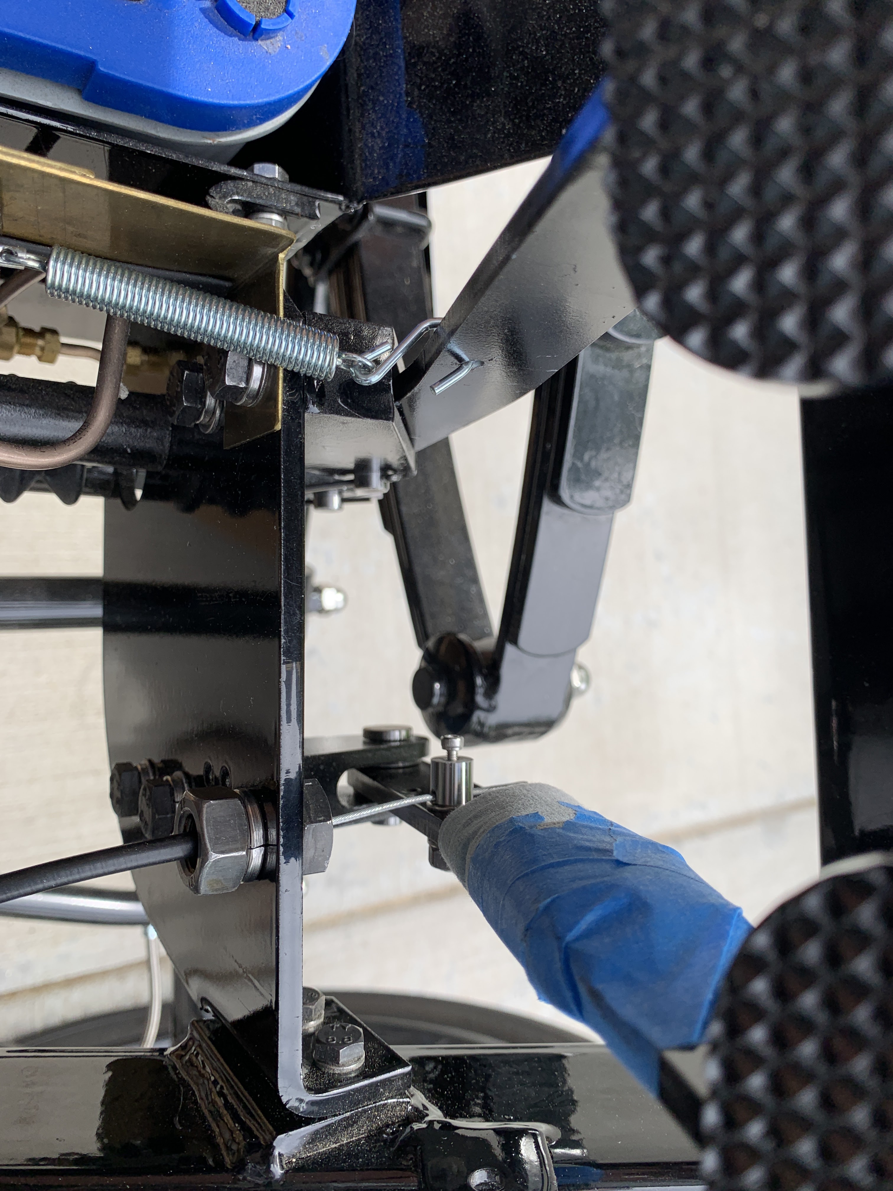
The regulator cable passes thru a nut/bolt combo. It has to be in place first.


I made a small/shorter replacement bracket.


I used the pre-drilled holes for the new bracket. It is interesting how just a 1/4 inch difference in height can effect the angles.


I disconnected the steam regulator (throttle) and stored it for now.
FLOOR PANELS
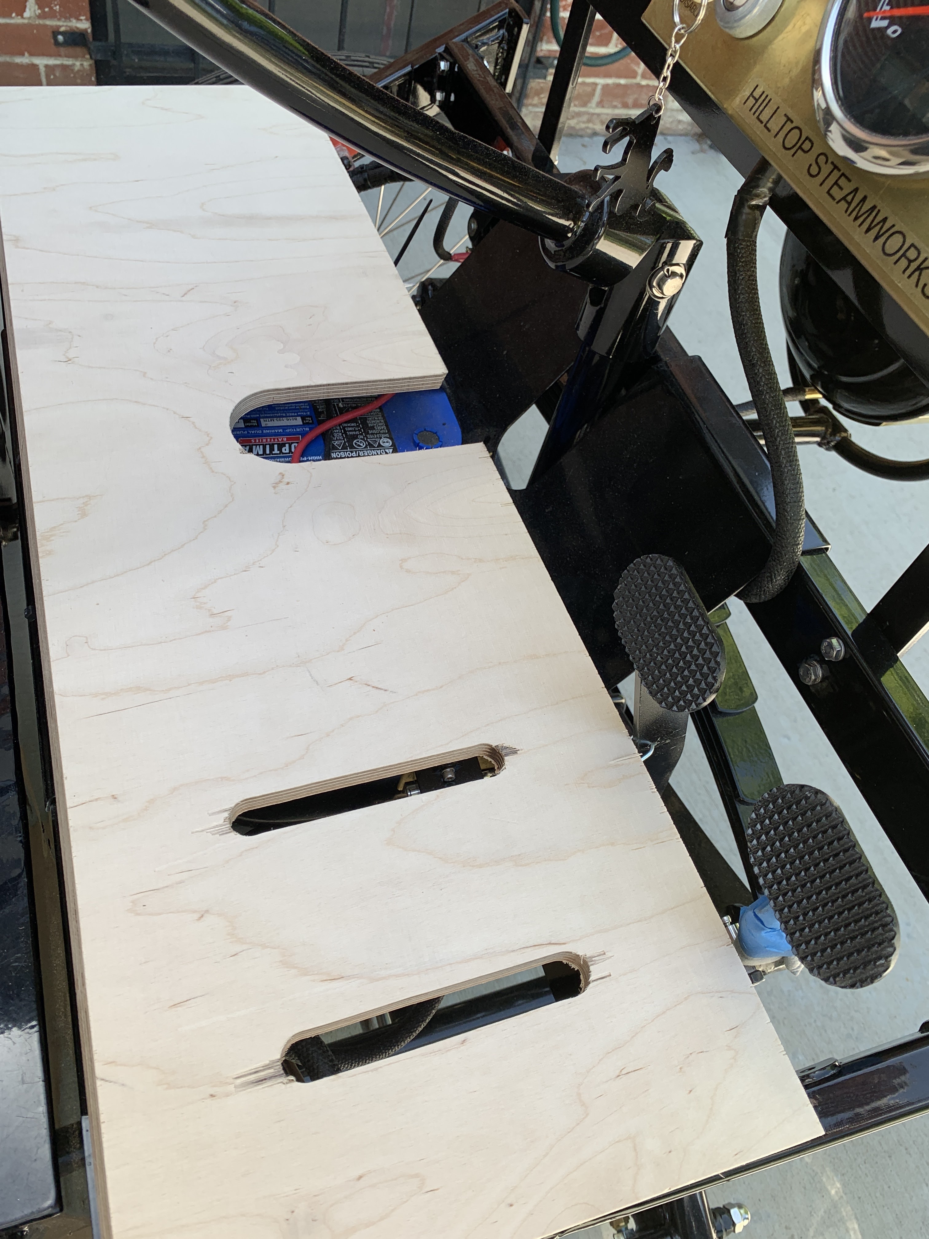
There are two floor panels. The main panel sits flat on two stringers, the front panel sits at an angle and supports your feet. The main panel has two cutouts. A circular one over the fuel filler and another over the electrical control box.
STW also gives you some blocks for mounting the side panels (next entry)

The main floor panel.
To prep the main floor panel, I need to add some support in each cutout for the inserts that "fill" the holes.
STW sent the insert panels, and a metal support bracket for the power console, but not the one for the fuel filler panel. Since I did not want to wait for them to send it sometime in the unknown future, I chose to create a replacement piece. I took a small piece of scrap, cut a circle, and glued/screwed it to the underside of the main floor section.


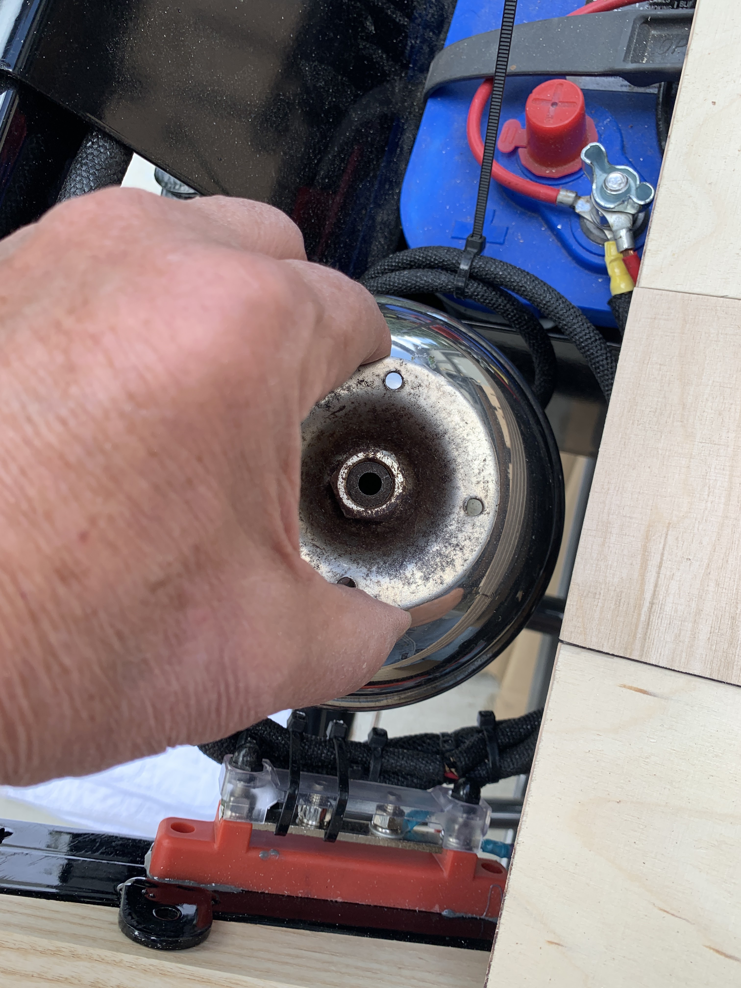
The front panel needed some additional work. I wanted to add a Carriage Bell on the passenger side. To do this I determined the place where the bell could sit below the floor and only have the small disc striker protrude above. I counter sunk the heads and constructed a brass gromit that will dress things up.


Colorado also requires an electric horn on any vehicle. For this I got a brass heavy duty pushbutton and mounted it right behind the steering pillar so it will be available to both passengers.


So here is a look at the front floor, with an additional mock up of the pressure gauge.

Some final adjustments. The slots cut for the pedals are a little out of alignment, and then I decided that I did not want to have to remove the pedal every time I wanted to pull up the floorboard. So I cut slots to allow me to slide the assembly on and off.


My plan is to paint the floor parts with a heavy coat of black as they will be directly exposed to splashes during driving. Then I will add a "diamond plate" rubber pad to the floor to keep the shoe damage to a minimum.
I decided that the first batch of panels would be the front section; the Front Panel, the Engine Panel, the Main Floor, and the Front Floor. I had already assembled the floor panels, so next I chose the Front Panel.
The Front Panel has four wooden "rails"around the perimeter and 2 in the middle. It is pretending to be a leather covered metal frame. There is no guidance on the placement of the inside rails, so I looked on-line at a number of antique units to find a place I was comfortable with.

First you need to locate and drill the mounting holes.


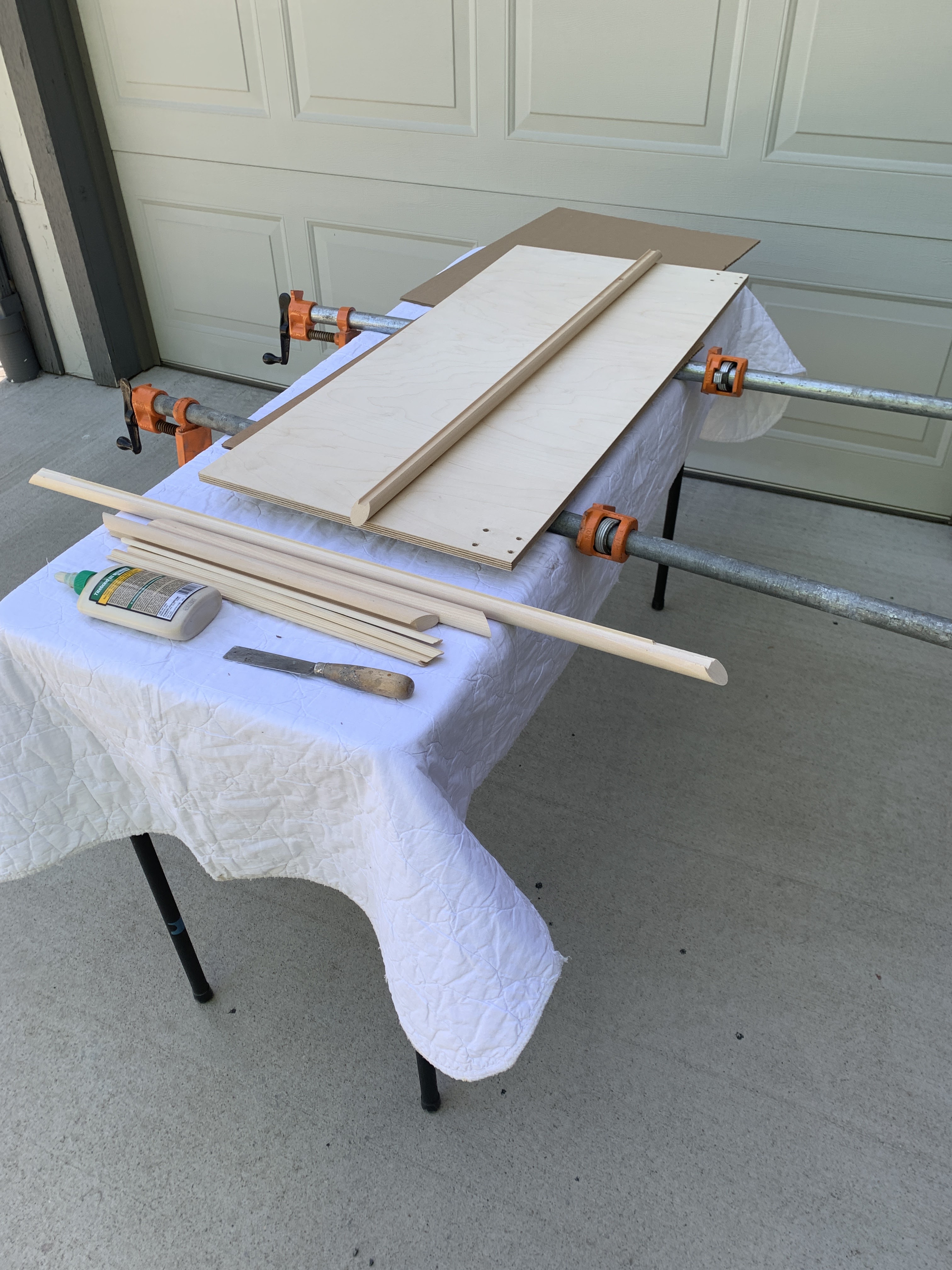
Once the holes are located, I assembled the panel and ribs. I used Titebond III waterproof glue and clamps for the perimeter, then used some small brads with glue for the center ribs.
I also felt I needed to add a mounting block for my Rubes Horn. When I bought it it did not have the bracket. I found a side lamp bracket that I ground down to work with the horn. It needs to "peek" around the side of the front panel with the hose going down and back to the horn bulb by the seat.


The Painting Process
All of my body panels will be gloss black with BRG (British Racing Green) accents. The louvers were made up months ago and have been in storage. I will add them to the side panels in a little while.
To prep for painting I will be using a 2-Part Epoxy Product called ESP-155. It is from a small company called Progressive Epoxy Polymers. The have a lot of products to the maritime (boating) industry and the ESP-155 is a product that soaks into the wood and seals it, acting as a primer. You can find them on the web, and must order direct.

The epoxy has a pot life that varies with temperature. The hotter it is, the quicker it cures. I am told that this is because the solvents that allow it to penetrate evaporate faster in the heat and then the curing occurs. I use a foam roller to apply. It takes about 3 coats to get a smooth (no grain) coat on wood. The last coat is pretty much a flood.
I setup a small table, and apply the coats in shade, then I move the table to direct sunlight for the cure. This produces a rock hard coat in about 4 hours, but I usually wait until the next day to apply another coat.
I am using Rustoleum Automotive Glass Black as a top coat color followed by their Automotive Clear Coat. I prep sand with 120, 240, 320 wet/dry, and 400 wet/dry. Following that I wash the piece down with Naphtha and paint the next day. Automotive paint works very fast. Mostly because of VOC's, I guess. You need to re-coat within an hour, or wait 2 days. It takes me about 4 hours to do multiple coats of black followed by the clear coat. Usually 6-7 coats in all. All this needs to be done in "quiet air" so I do it inside the garage using a respirator from Covid supplies and wearing an old pair of glasses, might have killed a few brain cells, but I don't seem to be missing them.

Finalizing the fit, I needed to deepen the grooves for the bolts in the frame and also add some relief for the battery holders.

 Floor sections - not real concerned with the final "polish" as this will be covered.
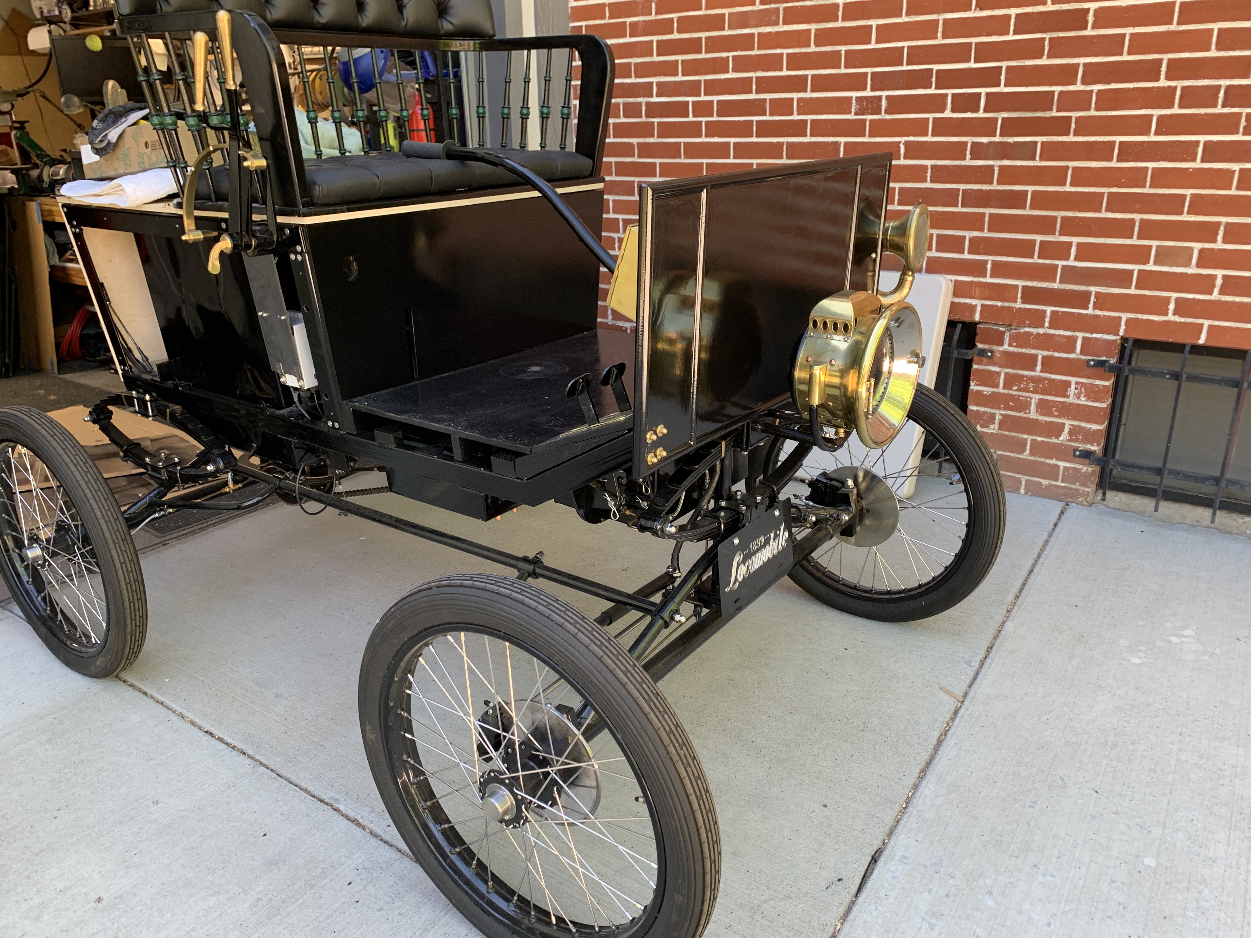
The front and engine panel took a bit longer.


The horn mounted. I really like the way the Dashboard fit inside the Front Board.
Then I added the clamp-on rear view mirror. I used a piece of leather to cushion the clamp. Here are some more views of the project so far.


This finishes up the project to date. Next I will add the diamond plate rubber floor and fit the brass hardware pulls for the access panels and engine panel. Then on to the rear deck and back panels.
Thanks for reading,
1 comment:
I like you solution to removing the front section around the pedals.
I also found the pedals did not line up with the cut slots and recut the slots 4 mm over. As for the pedals not being level I noticed that the brake clevis could be screwed further on the push rod, resulting in the clutch pedal moving forward. My first attempt was to move the mounting point for the return spring forward on the regulator pedal.
Post a Comment
Thank you for posting your thoughts on my build.