What its all about

Poppapope's Steam Car

Just killing some more time.

 Headlamp Bracket

A while ago I covered the reconstruction of a Solar 800 Headlamp.  

https://poppapope-steamcar.blogspot.com/2023/03/finding-things-to-do-waiting-for-boiler.html 

At the time I decided to electrify it and after shining it up, I put it aside until I could figure out how to mount it on the front of the car.


Taking a cue from Grier, I focused on getting some type of mount that attached to the point where the front of the frame and the front leaf spring came together. 


When I got the frame kits from STW, the studs provided for bolting the frame to the chassis were about 1/4 inch too long.  At the time I took the easy way out and used some larger nuts as big spacers to eat up the slack.  Coming back and looking at it, I decided to try for a bracket that would fit on the front edge of the assembly and was made of 1/8 inch steel. This way it would clamp over the existing plates and I could remove the "spacer nuts" as the clamp would use up the excess.  


So - Where to get a bracket?  

I scoured Ebay, Etsy, Model-T sites, Brass Era sites over a couple of months.  I never found an 8" Headlamp bracket that I could use as a starting point.   I studied the blog entries on Grier's blog, 

https://210doghouse.blogspot.com/2018/03/front-headlamp-mount-part-1.html 

where he modified one to mount on his Lyka.  

After assessing my welding skills (none) I went on a hunt for someone to help me out.  I talked with a couple of fabricators here in Denver, and found that unless I was doing a large project they did not have the time.  So I looking into the local "Steel Yards" to see if I could find anyone there.  In the past I have found that many suppliers of material, wood, steel, plumbing, etc have people woring there who are craftspeople and will do small jobs.  

I found a place - Altitude Steel - in Denver that was willing to supply and fabricate my little bracket. 

(Shameless Plug)


 I gave Jake some sketches on graph paper - napkin cad - and he was able to get my bracket built in a very timely manner.   It turns out that my measurement on a crucial portion was off by a 1/2 inch, and he graciously modified the initial bracket to fit.  (no extra charge).   I will use him again for any other steel projects, on the car or off. 

Here is the bare steel bracket, as delivered,  only some minor cleanup on the two rods that insert into the headlamp was needed.  It all fit, but I wanted a little play to make removal easier.  There are a pair of bolts (set screws) in the lamp to lock it all down so I am not worried about it rattling away. 

The bracket - 


Rough Fit - I opened the bolt holes a bit to allow minor side to side adjustment. 

Primer and Paint - Automotive Gloss Black with Gloss Clear Coat.  


Fit to the front mount - I was a little concerned about getting everything tight again, especially the original use of the bolts which was to afix the chassis to the leaf-springs.  However, the bracket was just tight enough to snug everything down.  


 And a fit with the Headlamp - 


Next I dressed the power cable,  and of course - tested the lamp. 
I think that the "focus" on the beam will take a little fiddling to get setup.


 Well, that's it for this week.   I have not heard from STW about any lights at the end of the tunnel but I know that reports of how busy they are on the production floor mean that mine is not the only project behind the 8-Ball.  

It is the end of September now, and fall-winter here in Colorado means that painting and finishing get more difficult as well as your fingers get stuck to bare metal!  

So - I have set my target "First Steam-Up" for our Memorial Day - the last Monday in May, 2024. 


Unless of course - I get a surprise package before then. 


Regards to all.

Thanks for reading. 

Poppapope
Denver, Colorado USA


More from Kit 18 - The Chain Drive

The Chain Drive 

Kit 18 was a bit of a hodge-podge of parts and sub assemblies.  There was the Wire Loom and Electronics, and the the Water Glass (which was just set in a box for when the piping actually showed up). Also in the kit was the Chain Drive and stiffener.  Finally was the Steam Regulator, and cable assembly.  Most of these pieces and parts were not usable until the Lyka was further along. 

However, after sitting and looking at the big empty hole where the boiler and burner belonged, I decided to fit the chain, at least for now.  I think this was a goo idea as it was a couple of links too long and required quite a bit of playing with.  If I had waited until the boiler and burner were installed, I would have needed to work under the car on my back.  As it was I could get everything fitted easily and can remove/replace it quickly when the boiler comes in. 

Based upon Grier's experience I went to the McMaster-Carr website and ordered a 1/2 link of a 12B chain.  This turned out to be necessary.  

First step -  Use a string to help pull the chain around the small-end engine sprocket. 


 Then loop the chain around the differential,  and do a test fit for length. 


A side view - pretty droopy. 


Here is the 1/2 Link along with the coupler provided by STW. 


Here is the 1/2 link installed after removing the excess.  You have to make sure you end up with the right parts next to each other. 


Chain Tension-er -  There are two brackets that get a ball joint and then a tension rod is run between them. One ball joint fits to a small bracket in the engine mount tube that is in-between the chain runs.  The mounting bolt must be ground down and a 1/2 thick nut used in order to avoid interfering with the chain travel. 


After grinding down the excess bolt length and pulling the chain just tight enough, The droop is gone and the chain will clear the bolt. 


So finally, the chain in place between the differential and the engine, checking the alignment.  If I need to remove it to install the boiler and burner system, I will be able to hook it back up without a lot of crawling under the car. 


Leaving it hooked up for now.  


Thanks for reading,


Regards,

Poppapope
Denver, CO USA


The Boilers are a-coming - soon?

 Boiler update - 

I heard from Steam Traction World that the boiler design has finally been approved and the boilers were in production.  It seems that since Brexit, there are now TWO agencies to make happy, one in the EU and one in the UK.  They each have similar requirements, but must be dealt with separately. 

Dean, the director of STW was kind enough to send me a picture of the boilers underway. 

Hopefully, now that the details are worked out, the remaining kits can get organized and packaged without further delay.  We have stalled waiting on the boilers with only piddling stuff to work on for the past year.  It will be good to back on track.  


Brake Light 

During tests of the electronic package I designed, I discovered that the switch I had configured on the brake pedal was not going to work.  The amount of movement required for switch contact was only about 1/8 inch.  I am concerned that the vibrations in normal travel will result in false indications.  

I found a more conventional brake switch that has a spring-loaded system where the contact is made after about 1/2 inch of travel.  

The original attempt: 


I removed that bracket and built a new one to hold the larger switch.  The switch and bracket both have a little bit of "springiness" to allow the play in the pedal.  


Playing with the Sight Glass Assembly

A part of Kit 18 was the Sight Glass Assembly.  This consisted of two very hefty metal parts, one brass - one stainless, a glass lens, gaskets and a sensor system for the water level.  

The hole in the back is for the sensor.


Steam Traction World had provided Black Oxide bolts, I replaced them with Stainless & Washers.


Water level sensing is done by using an IR (infrared) led and sensor.  The prism lens changes how the light refracts when immersed in water.  The change in levels is sent to the circuit box (in background) where it will open or close a relay (depending on the change) - if the relay is open, the flow of electricity to the burner relay is interrupted.  This circuit is in series with two other control points, the pressure switch and the burner enable switch (on the dashboard).  

The water level sensor control. - Three Off-the-Shelf parts in a small plastic box.

The end result is three places that need to be in agreement in order to fire the boiler.  I am also contemplating another level sensor, one that also had high and low points, in order to control the water bypass valve. 


However - all of this goes in AFTER the boiler. So we will just have to keep on working on the little pieces that will help it go all together. 


Thanks for reading,

Jim Pope
Denver, CO USA


Kit 18 - The Wiring Loom (Harness) - Dashboard and Controls

The Stock Wire Loom (Harness) - 

First - let's talk about the way the Lyka works from the perspective of "How does the burner work?"  The heat source for the boiler is a Riello 40 Model G10 furnace burner.  It has a rated output of 55-120 KW - which translates to 187000 BTU/hr up to 409000 BTU/hr. The burner runs on 220V (gotta love the UK and EU) this is sourced by an inverter that takes the dual 12V batteries and provides the 220. The inverter is turned on and off as heat is required, thus firing the burner in turn.  

The fuel source is Diesel (Light Oil).  The fuel "circuit" includes a tank, filter, and pump internal to the burner unit.  There is no "pilot light".  It is electronic start and burner status is sensed with some type of photocell.  There is a squirrel cage fan built in to force the heat into the shield area under the boiler. It is deflected upwards, thru the multiple fire tubes, and out the "chimney" in the rear deck of the Lyka. 

After I get the actual burner unit, I will do some open-air test firing to see how far the flame goes. 

The stock electronic package is comprised of a small box with 4 fused circuits and two switches on the outside.  Internally there are two relays.  One relay is the Main circuit, the other is the ACC/Lamp circuit.  The "main" switch turns on the Main Relay and enables the ACC Switch to turn on the ACC Relay. 

The Main Relay controls voltage to the burner.  The control circuit has two additional points of interruption,  The water level system and the over-pressure switch.  Either of these will interrupt the power to the relay and hence to the burner.  

SO - if you have a cold boiler, with water in it, and you turn on the main switch, the burner will run until you run out of water (1/2 way) or reach max pressure.   

If you turn on the main switch and then turn on the ACC switch - you get power to the Lights. 

All in all a fairly automatic system.  Just keep adding fuel and water.  

Water Level Sensor (more details later)


My Modifications

My requirements for mods were defined in a previous post, but I will review them a little here. 

1. Manual Cut-off of boiler.
2. Water and Fuel Level Display
3. Manual control of light circuits.
4. "Key Ignition" switch. 
5. Speedo and Odometer. 
6. LED Indicators of Burner Enable / Burner Active / Lamps
7. Brake Lights (Always available if Main is on). 

Constraints: 
1. System must minimally change the provided control box. 
2. All "Loads" should run thru a relay. 
3. Switches just control relays, relays control loads. 
4. Tanks must be removable. 
5. Wiring should be neat and labeled. 
6. Grounds will be home-run as chassis is powder coated. 
7. Additional circuits should be in weather-resistant boxes. 
8. Dash system should be removable. 
9. There should be "beak-points" for test access and system bypass. 

The first step was to pre-wire the chassis.  Identify the cable runs, deternine the access to the final locations,  group the cables passing thru each major point,  pull and protect,  dress and terminate, and finally label. 

I established a central access point for connection and test as well as bypass.  I put a set of barrier strips on the inside of the chassis, on the opposite side from the pressure valve, sight glass connection and general future piping.  At this location all loads and control circuits are accessible and can be bypassed if needed. 
 
So I can completely remove my mods and the Lyka will still roll merrily along. 


The connections to the Lyka lights, brakes, and power busses are on the right side.  Connections to the control circuitry are on the left. 

 
 The stock control box now has a bit more cable traffic, but only two new connections inside, 
one for the ACC power buss, and one for the burner override connection. 
(The Yellow cable is the battery charger input point - A cigarette lighter socket)

The Remote Connection / Relay Box

Next I assembled the box I wanted for remote connections.  I wanted a central location for the umbilical to the dashboard, and also individual relays for the Headlamp/Tail Lamp circuit and the Side Lamps. In my design I basically have what I call a Low-Amp and a Hi-Amp circuit.  The Stock controller box has three circuits inside it.  A Low-Amp, controlled by the Main Power switch - this enables the power to the burner relay, Hi-Amp to the burner and it also feeds the ACC Switch.  The ACC switch controls a relay which provides Hi-Amp to the lights. 

So Switches are Low-Amp to Relays,  Relays control Hi-Amp to Loads/Burner. 

In keeping with that concept, I wanted the dash system to run Low-Amp to Relays in the Remote Box and the relays to enable the ACC Main Hi-Amp power to go to the various lamps.  This is because all of my lamps are converted to electric, but might use a variety of bulbs.  Since I wanted to use some "vintage" switches for lamps on the dash, I wanted only Low-Amp circuits to go thru them.  

First the box - 


Then a circuit for each load with relays, LEDs and connection points. 


Then fitting it in the box along with a junction strip.  The junction strip contains the color-coded multi-conductor cable that is the umbilical to the dash system. 


 I was working upside down because the other end of the cables were already attached to the car. 


I decided to mount the box to a plate that was suspended from the main cross bar of the chassis/body. This will keep the box safer in the future when things get crowded in there.  I mounted it as far away from the engine cylinders as possible. 


The Dashboard

Design criteria - 
1. Needed to be smaller than the front panel of the Lyka. 
2. Needed to be able to be removed and replaced easily. 
3. 1 connector umbilical.
4. Fit into the general color scheme of Black and Brass. 
5. Contain the controls previously determined. 
6. Build from available pieces and parts. 
7. Be angled for viewing - like the Clock.  
8. Look cool.

So - Starting with the board itself - needed to determine an optimal size.  I also needed to source a piece f quality plywood.  I chose a good clear Birch Veneer plywood as I liked that it had tight glue layers as seen from the side and two clear sides, no knots or patches. 


Then I found two pieces of 1"x 1/4"aluminum bar to cut the brackets from. 


I decided to round the corners so the brass banding I am locating will be easier to install after the finish is done.

In keeping with my new wood finishing process, I coated the dash with the ESP-155 Epoxy.(see Seat Log)
After giving it a few days to cure, I sanded it down and used Rustoleum Gloss Black Automotive Paint. 
(I think I need to perfect my sanding technique - but it looks pretty good.)
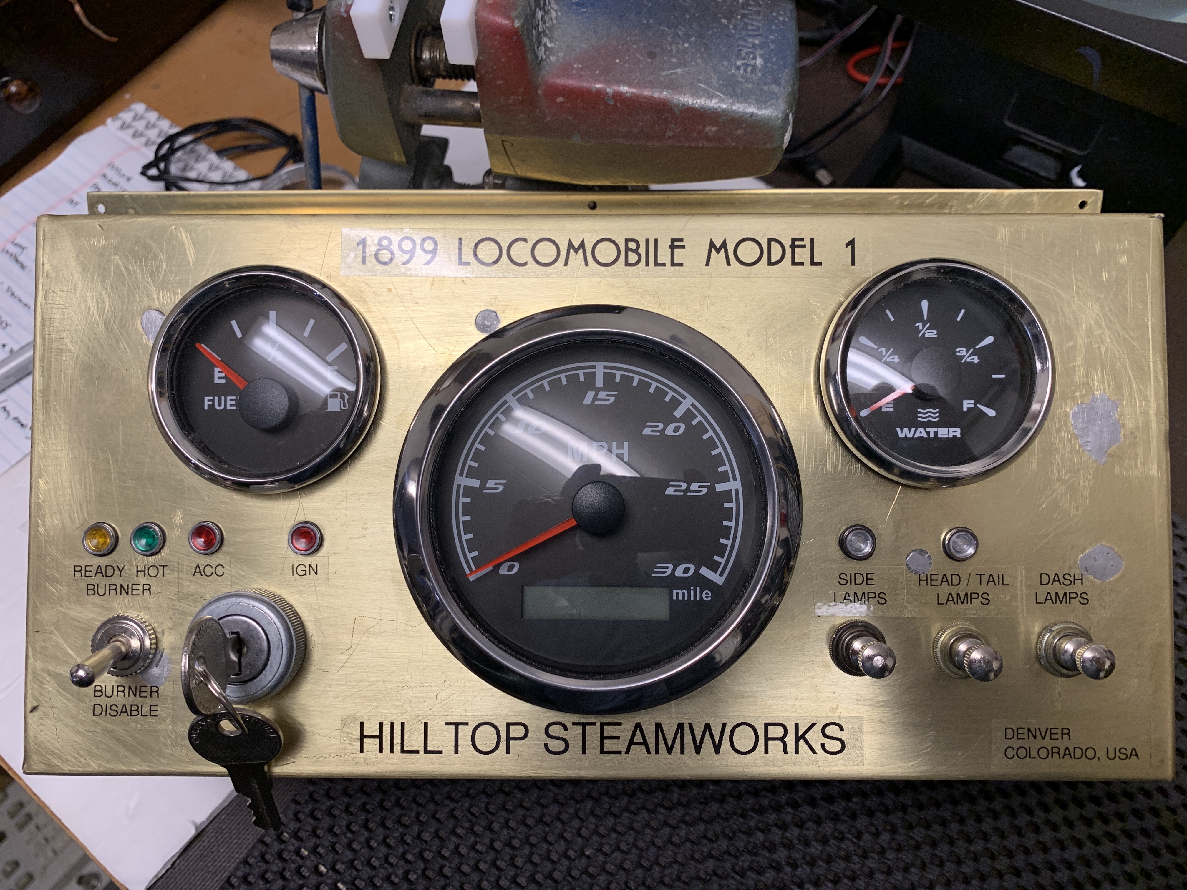


Control System

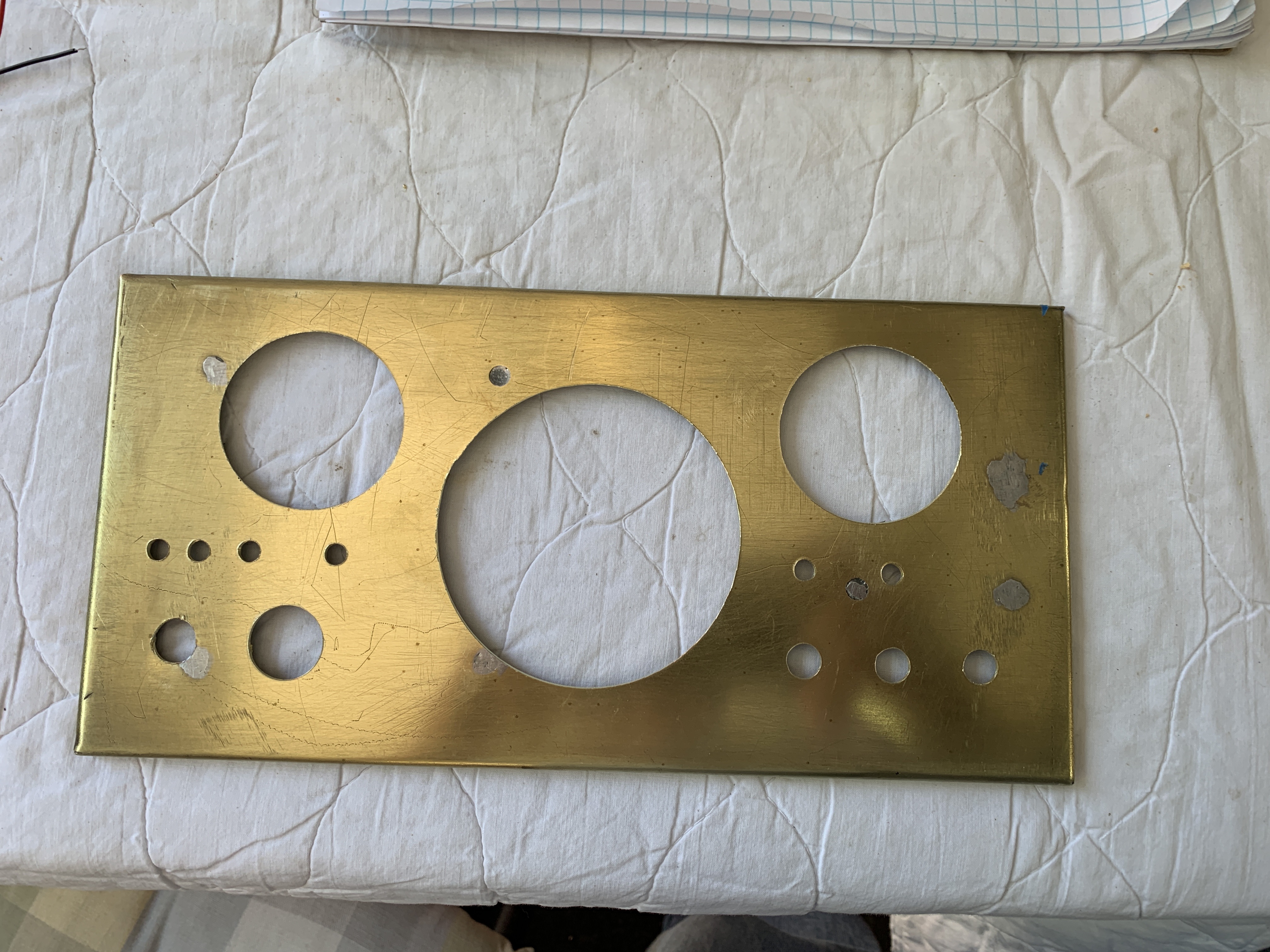
The control box will be mounted on the dash.  I made it from some available scraps of brass.  I used JB-Weld in stead of actually soldering as I thought that having to solder multiple seams and keeping things from warping/melting might be a PIA. 

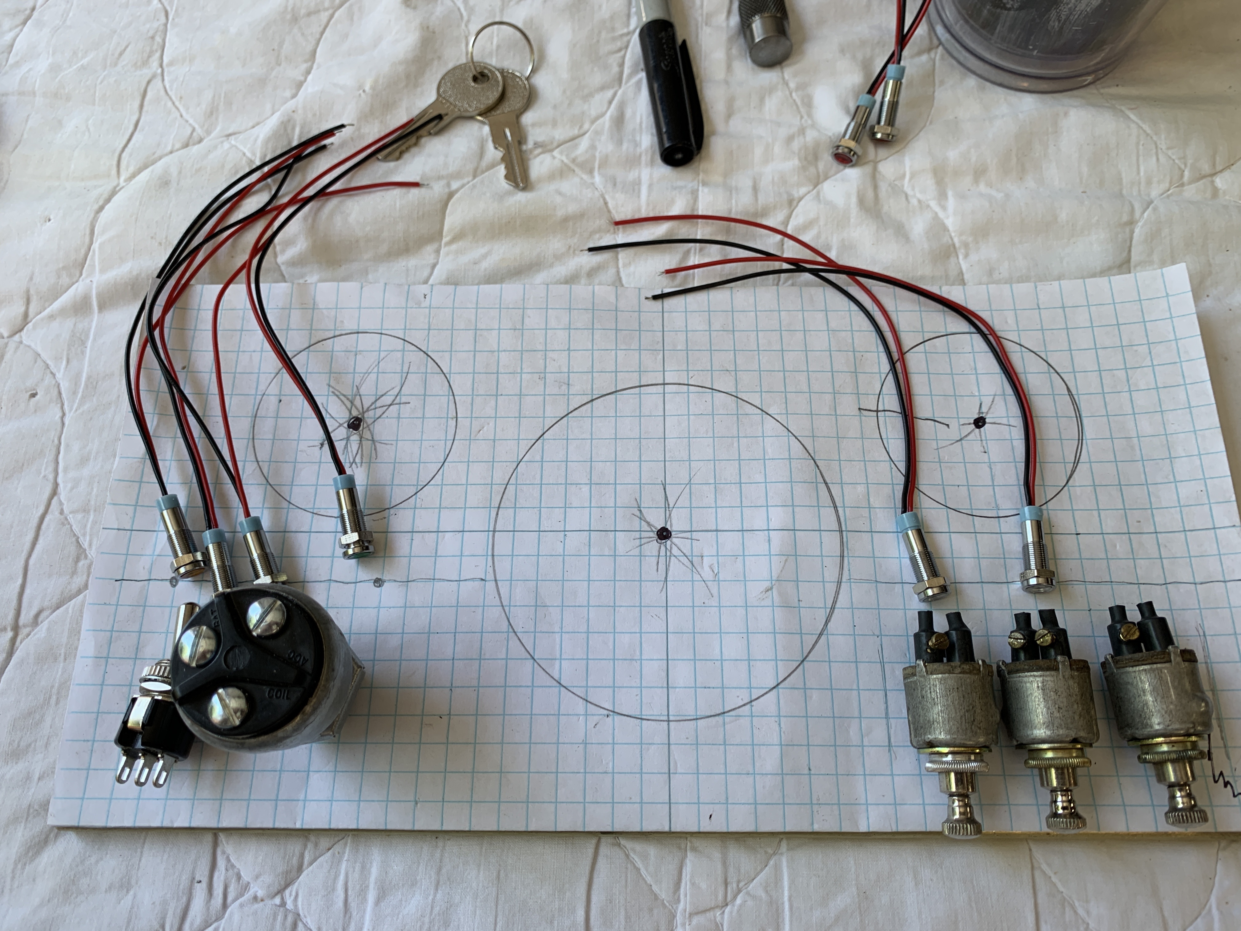
I decided on a layout - the Mickey Ears one.  I am putting the ignition and cutoff switch on one side and the lighting switches on the other.  I had to play for awhile to get the viewing angle to match the clock I had, and then came up with a way to secure the shell to the base, and still be removable.  I attached some "L"Brackets made from brass angle to the base and then drilled and tapped holes for socket screws.  


Unfortunately, the piece I have for the front panel is in the roughest shape.  Some previous holes that were soldered closed and scratches.  It did have the nicest corners and allowed for the box assembly to go quite smoothly. 
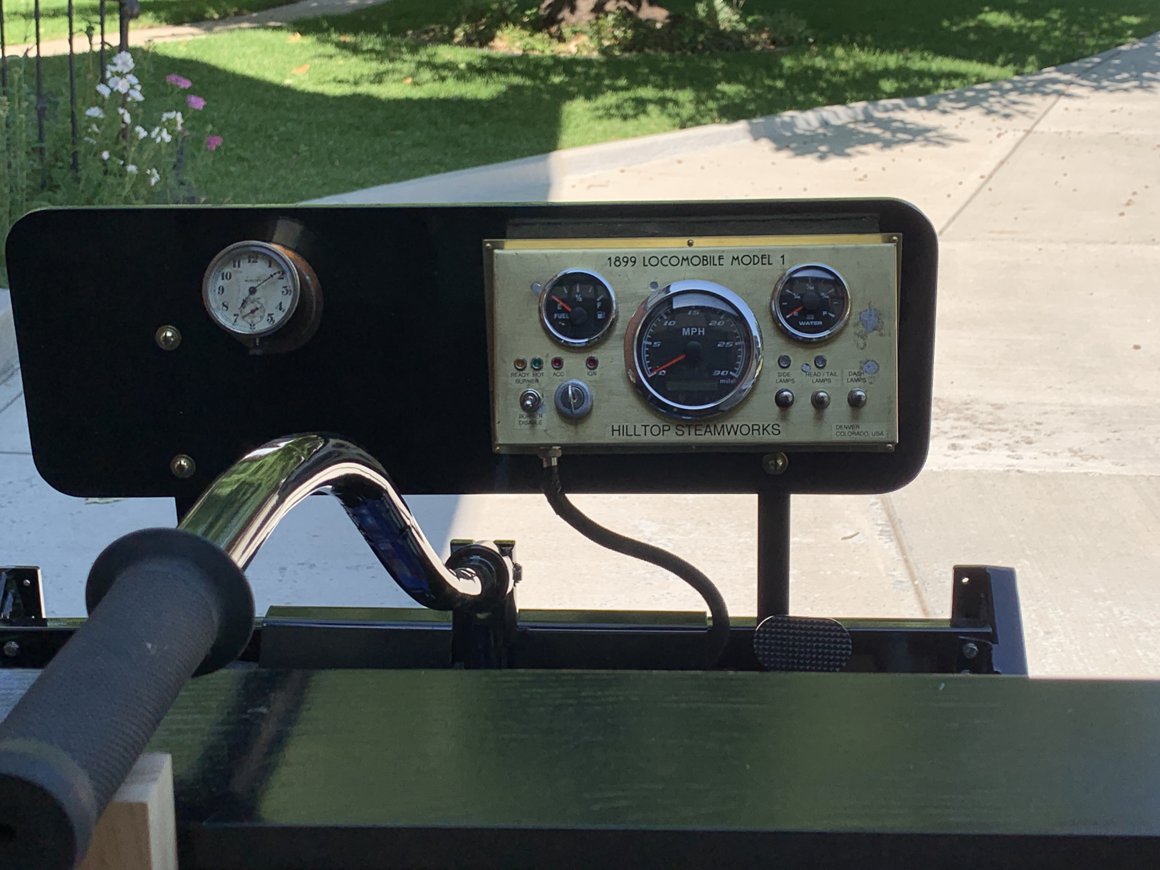


The end result:


And in place: 


Well, 
That's about it until I get another shipment.  I may have to go back to playing with boats and miniature steam in order to keep my fingers from itching.  
 
One last picture -  The brass banding came in, I added counter-sunk holes for brass wood screws.  Here it is in place: 


Thanks for reading,

Poppapope
Denver, CO
USA