Breaking the Lyka down to its SubSystems
When I look at the internal components of the Lyka, I see a few SubSystems that work internally to support the car. Over the last years, I have concentrated on the electrical system, mostly because the other systems were yet to be delivered. They are:
Steam System
Drain System
Feedwater System
Oiler System
Burner System
Each subsystem has a number of components that must be sourced and laid out to study the interconnections. Then I will build each system "offline" so to speak. The goal is to be able to work on the pieces up to the pint where the boiler must be installed. Then the systems will be disconnected if needed in order install the boiler and burner shielding. Finally the system will be re-attached if needed.
Steam System
The Steam System is comprised of the Boiler, Burner, Sheetmetal shielding, and piping into the engine. I can not install the actual piping before the boiler, but I can stage the pieces in preparation.

The primary connection for steam is the 3/8 inch piping coming off the top/center of the boiler. This connects to an elbow and then travels thru the regulator into the engine. Branching off is the Safety Valve and associated blowdown spout.

The output of the regulator is linked thru a short pipe to the Steam Inlet Manifold. This piece will distribute the steam to the top of each valve chest. There is an additional small pipe connection to inject steam oil into the flow a little at a time.

Other parts of the Steam System pertain to managing the water level in the boiler and distributing steam for the Pressure Gauge and the Pressure Switch. A lot of this stuff will need to be placed after the boiler is in place. But first I need to stage the parts to be sure all is ready.
Because we have lost the Lyka "Champion", no one is verifying the drawings to check for reality. As a result, there are pieces missing in some of them.

Not that we can't figure things out, right?
All the pieces are here, but I have to be careful not to get too impatient, and make a fundamental mistake that will come back and bite my butt in the future. So once again I lay everything out on the table first.

I won't be able to attach the Reflex Glass until later, but I want to fit the elbows to it first. One thing I noticed was that the threads on the glass back plate were very shallow. When I asked STW about them, I was told that it was a difficult task to cut them due to the need to align to the holes in the chassis and the cut-off valves.


Drain System
In the engine, when it first starts up and is getting warm, thee will be a collection of water. This is the condensation caused when the hot, wet steam makes contact with cold cast iron metal in the cylinders.
At the bottom of each slide valve chest there is a drain connection. This allows the water to be dumped thru pipes and a valve out on to the ground.
The first issue encountered is that there is a clearance issue on the initial drain connection. Where the elbows screw in, there is only partial clearance into the hole on the cover. In addition, there is a small bracket that holds the lubricators and it is interfered with. I had to rework the hole for the elbows in order to get them to screwall the way in. Then I ground the protruding part down to the plane of the face-plate. This allows the bracket to fit as well. I used X-Pando to solidify the connection.


After prepping the face plates, I cleaned the face of the steam chest and applied a coat of X-Pando. Then the face plates were re-attached and bolted down tight. The whole thing was left overnight to set up. Finally the Flare Adapters are tightened in place with SteamSeal.


Once the SteamSeal on the flare adapters has set up, it is time to link up the individual drains. The pipework is simple, the drains connect to a tee that then passes the steamy water to the valve. STW has temporarily shorted me on the valve bodies, so I have picked up some as placeholders. These will allow me to bring up the boiler and test most of the connections and the engine.
I pulled together some of the parts for the drain. Of course you also need to stage the other systems so you can see how the pipes route around each other.


I pulled the fuel tank, in advance of working in the fuel piping, this allowed greater access to the drain pipes.


Because STW was somewhat disorganized, when I got Kit 19, the valve bodies were missing. I communicated to the shop floor that mine were not to be found, and they checked the other boxed sets on the shelf that were waiting to go out. No valve bodies there either. So we can see yet another effect of not having a product "champion". There is no one there at really understands the Lyka. No one has actually built one of these. Luckily, we are past the really difficult parts, like the engine, and the remaining pipework is rather straightforward.
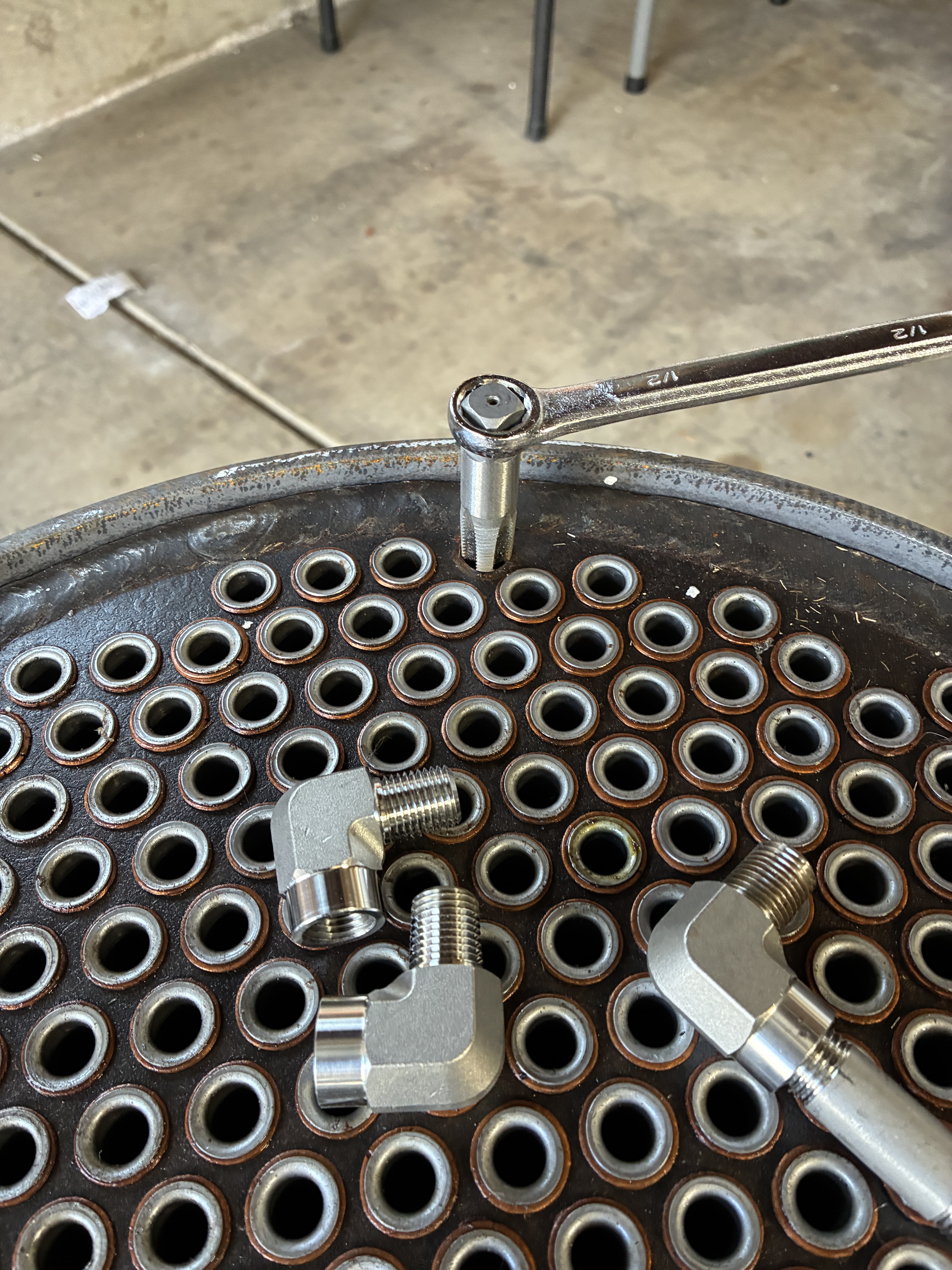
Where this leaves me is having so source three alternative valves, two for the boiler blow down, and one for the drain system. The internet yielded a couple of choices, and the replacements were ordered. The three blow downs are in fact "right angled needle valves" and they are directional.

The drain valve needs t be accessible from the driver's seat. The shaft extends up at an angle so you can reach it while driving. This valve is mounted on a bracket. In the original design, you were expected to mount the bracket to the wood of the floor pan. That is fine if you never need to move the floor. However, since access to the batteries, brakes, and a lot of other parts requires moving the floor.
I opted to add an additional horizontal bar for mounting things.


I confirmed the placement by temporarily placing the lower reflex glass valves in place, The pipewok is getting close, but everything clears. I will have to build one piece of pipework. That is because the orientation of the new valve is different from the original STW model.

Feed-water System
The feed-water system exists to get water back into the boiler so you can keep driving along. There are two tanks located on the sides of the boiler. Pipes traveling under the boiler connect the two tanks, and then water is drawn into each mechanical pump located in he lower parts of the engine. There is also a hand pump that allows for the initial filling of the boiler.
A fellow Lyka builder, Grier Fleischhauer (his blog is linked in the sidebar), produced full diagrams of the Feed-water system. He has graciously allowed me to show them here:
Feed-Water system with bypass valve open.

Feed-Water system with bypass valve closed.

The bypass valve is controlled from a small lever mounted with the gear and brake levers. When open, it allows the pumps to circulate the water back to the tanks, when closed it forces the water against the check valve, back into the boiler.
In the electronics section of this blog, I designed a circuit to control an electronic bypass valve. I have sourced a valve that is "normally open" - this means that the valve is open, and then closes when a voltage is applied. It opens again when the voltage is removed. I mounted the valve on the "downward"side of the manual one.

The majority of the Feed-water system is in the area below the boiler and burner shield. In order to lower the amount of time I spend on my back under the car, I am staging all the pipework in advance. Then I will remove the tanks and have everything ready up to the connection for the boiler check valve.


One of the items that were not sent by STW was the Hand Pump. From what I can tell, there was an effort to build these in-house rather than source externally. Initially I received some parts but not a complete pump. Back in an early kit, there was a bracket sent that was pre-drilled. The pump base I received did not fit these holes. Since I am impatient, I found a source for the original pumps, John Rex Engineering. The pump I got from them was an exact match. I only needed to swap out the straight handle for the bent one from STW and everything dropped into line. The pipework needed bent and flared, but all is now in place.


Another First! - Making a flare for the connections. Never done that before. Now I have. I di discover that regardsless of the tube type, hard or soft, it all goes better if you "anneal" the ends first. Heat them up with a torch and let them cool. Saves on the elbow grease.


Everything is getting close quarters, but the pipework is in, and while clearances are tight, so are the connections.


I am going to end this installment here, and continue with the Oiler system and Burner installation in the next two.