March 2
Winter is winding down. Days are getting over 50 degrees, which is nice because I work with the garage door open and the chassis wheeled out on the driveway.
I am sure that others have the same experience with garages over the winter. You tend to just dump things in there with the plan to go back and straighten everything out "later". I am no different. Stuff I think I might use gets piled up and eventually it gets difficult to move.
So I spent about 3 days cleaning out the boxes and putting away all the tools that got dumped after use. Then I uncovered the headlamp I got for a song on EBay. Now I know that the original Model 1 (the Stanley Stanhope Model 1 from Locomobile - that which my little girl is based upon) - did not have a headlamp. It just had side lamps.
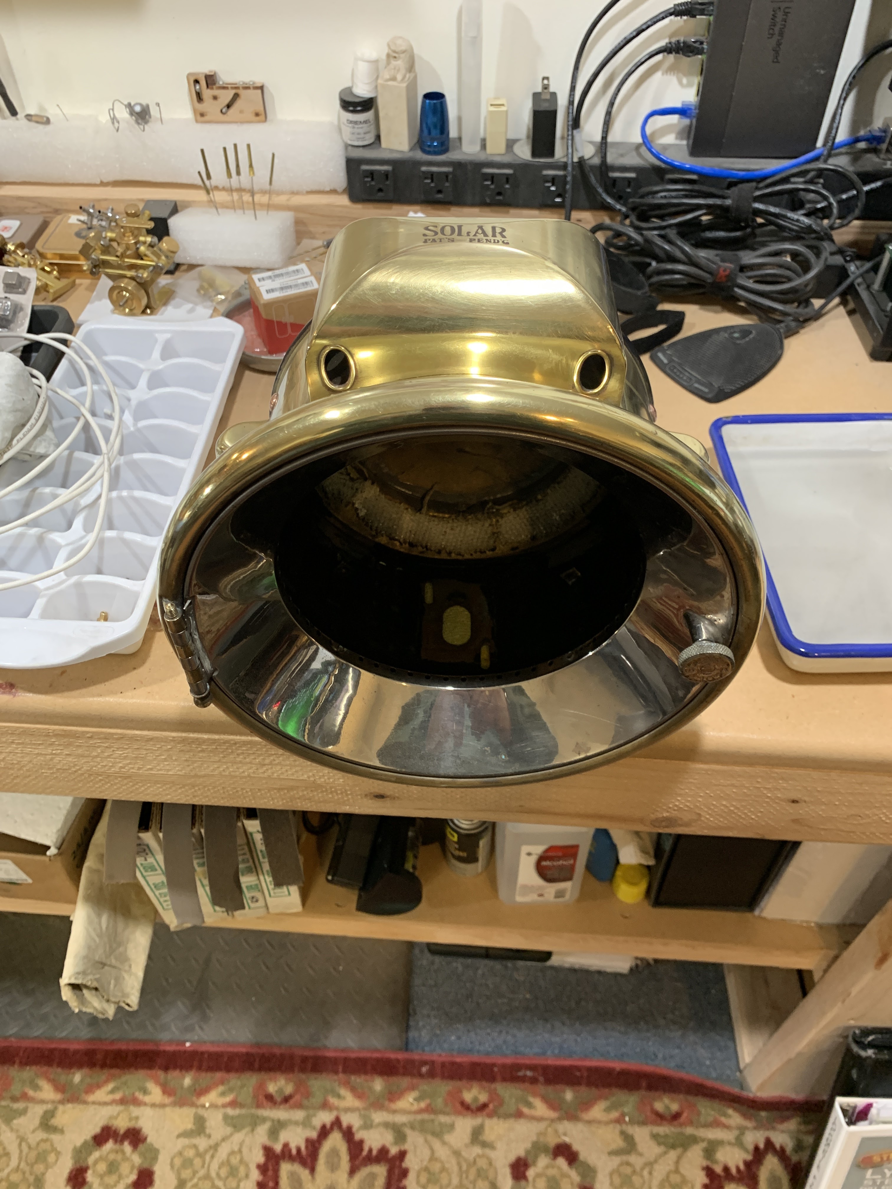
However, many of the examples I have seen, both of "originals" and replicas, have one and sometimes two headlamps. So - after looking around for a while I picked up an 8 inch SOLAR that looked to be in reasonable condition. Well - If I had looked at the pictures a little better, I would have seen some cracks. To be fair the ad did say "some repair may be needed".
A first look - Honest "patina" - some dents visible.
The lens is totally intact.
So is the reflector.
I got nervous about scratching the back of the reflector, so I wrapped it in plastic wrap.
Here are the cracks that I found. Wonder if I can solder them?
The first step in trying to repair the cracks was to remove the old patina and get everything down to clean brass. I found that the "flap" was moveable, and spent a bit time cleaning the edges of the cracks in the hopes that solder would stick efficiently.
I looked into types of solder and found a company called "Muggy Weld" that made alloy solder rods and flux. I chose their "Super Alloy 1" for a variety of metals. It has a low melting point. Since I was looking to secure the "flap" and I did not think that it would get very hot (I was planning on converting to electric), the low melting point made it easier to work with.
As you will see, I am not as good as I thought I was.
Not the smoothest solder job I have ever done.
I used a Dremel with a sanding disc to smooth out the big blobs.
After cleaning up the solder job, I worked on the remainder of the shell. Even though the cracks are sealed and smoothed, it looks like the back of the light is going to have a fair amount of visible dents. I decided to paint the back dome a gloss black. This might be a little different than standard, but it will look pretty good along with all the other gloss black on the car.
So - on to the interior. I wanted to change acetylene burner to an LED bulb. I also wanted to keep as much of the interior structure as possible. I went to Restoration Supply Company and found a small adapter that would attach to the post and had a halogen bulb. I wanted an LED bulb so I removed the halogene fixture and purchased an LED bulb and matching socket off Amazon. After using some JB Quickweld to attach the socket to the bracket, I tested it on the original post.
In order to have the bright spot of the "light" at the same height, I needed to make a small extension to slide over the original post (after unscrewing the acetylene burner). I use a couple of brass pieces, a tube and a post.
(I just noticed the rule had slipped, but the measurements equate)
Next I needed to route the wires. I also wanted to have a set screw to keep things from "rattling around." To accomplish this I added a few holes in the larger tube. Then I used some 2 conductor wire with a very tight jacket and worked it in thru the gas pipe and out to the underside of the lamp bracket. Some heat-shrink to protect the solder joint and we are ready to go!
Now to try it in the headlamp itself. First I cleaned the lens, then put everything back together. That was when I discovered the reason for the original cracking. The reflector is held in by 4 pieces of lead, arranged around the interior of the back. When I originally disassembled the lamp, the screws holding the pieces were really tightened down. This pushed the reflector against the retaining ring (and the padding) and in fact, it pushed out the back.
So - I have been careful to not over tighten the clamps.
A 12 Volt battery is all that is needed to light-her-up!
So much for this post.
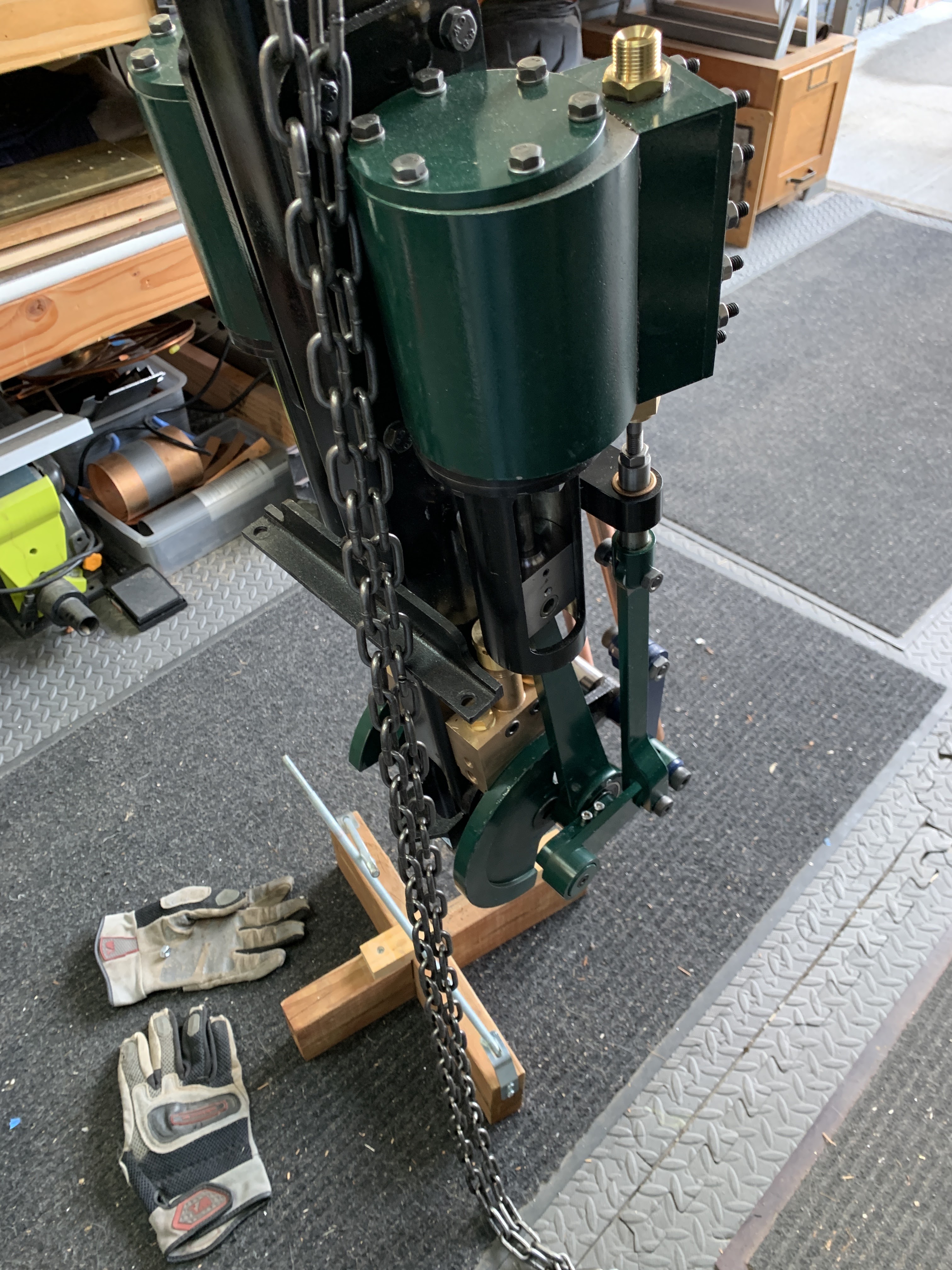
Next time the weather is good (maybe this weekend?) I plan on dropping the engine into the chassis.
STW is has sent me the next kit, KIT 14 with the reversing linkage and brake handle, so I had best have something to connect to.
Until then - keep on steaming.
More to come.
Poppapope
Denver, Colorado
USA