
A Review
Up to now we have fully assembled the Lyka, hooked up all the piping, dropped in the boiler, finished the steam connections and are ready to mount the burner and make some steam.
If you have not done this then you should drop back a couple of episodes, review the connection process and the overall build.
So here is my baby, without the burner.

Mounting the connecting the Reillo Burner
The instructions from STW on mounting the burner are somewhat scant. In addition, they tell you to RTFM and also tell you to mount the burner upside down. Well, you need to RTFM, but you CANNOT mount the burner upside down.
When you read the manual and documentation on the burner, you will see that it has been written for the HVAC professional and not a hobbyist like ourselves. So there are a number of terms and conditions that may be undefined in your normal vocabulary.
First there is the mounting process:
The burner, when installed right-side-up, has a single bolt holding it in place. However, the burner was not designed to be mounted on a bouncing vehicle, with the burner on its side. The original design uses the weight of the burner to hold the seal tight against the mounting plate. When you put everything in a 90degree rotation, the forces of gravity are wrong and there will be undue stress on the mounting bolt and plate.
To mitigate these forces, we need to fabricate a means to fasten another bolt on the opposite side from the factory mounting location. If you turn your burner over, you will see a 10mm threaded hole opposite the mounting bolt. There is also a hole in the mounting plate in the same location. But they are facing the wrong ways. You need to make a "L" shaped bracket and use two bolts to hold everything in place.
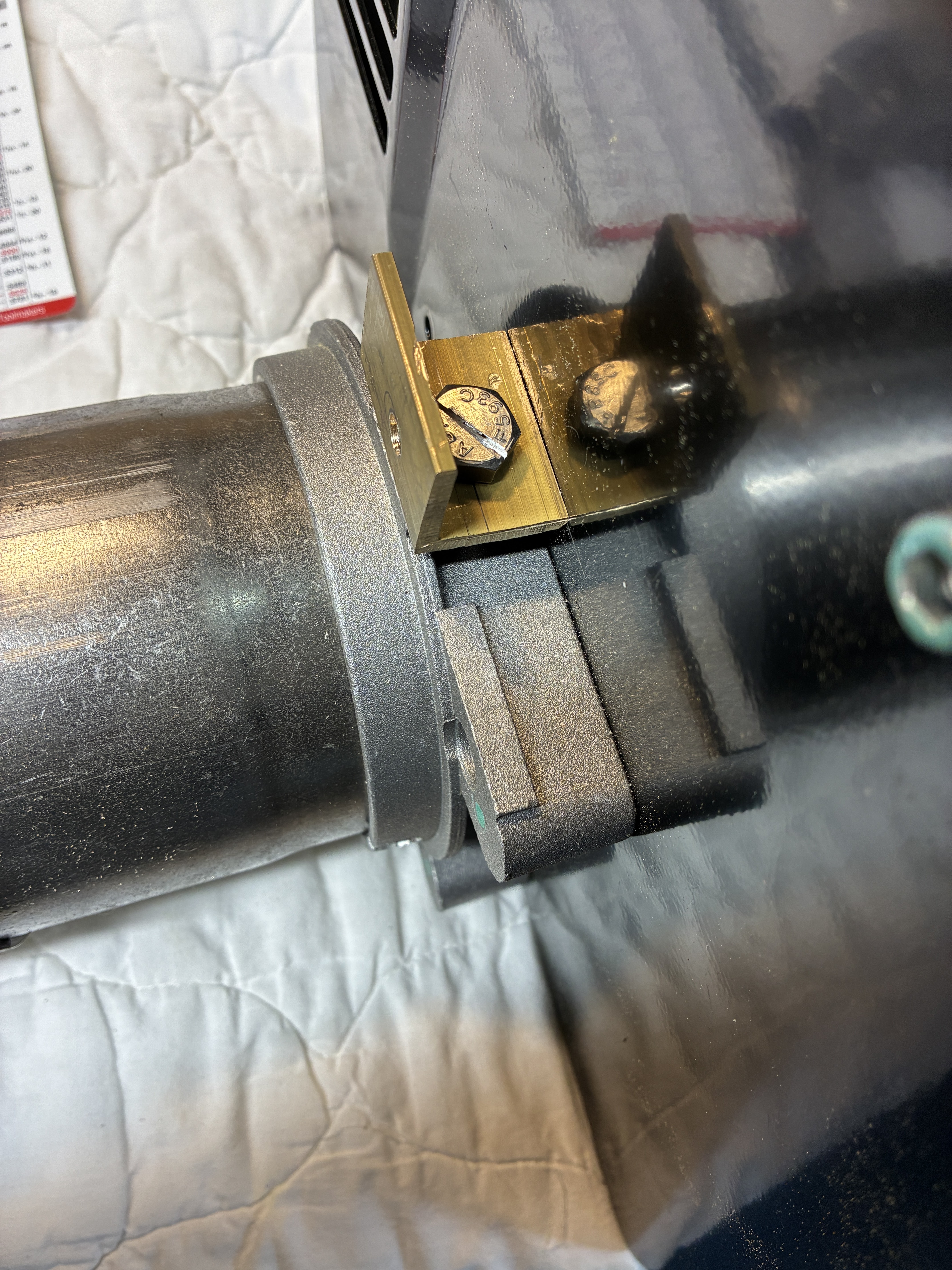
This is a really tight spot to work in. Here is a picture of me holding a piece of brass angle in place while trying to figure out the way that works best:

The factory bolt is at the top, my finger is pointing to the location of the added bolt.
The trick here is how to get access to one of the connections in order to remove the burner in the future. I chose that the connection to the mounting plate should be "permanent" and the bolt into the burner should be removable. The bracket will have a countersunk bolt into the mounting plate and then I will use a bolt with a slot cut into the head for fastening the burner.


The mounting plate also must be modded a little. You need to cut away for the bolt head on the support strap. Both the friable gasket and the mounting plate need to be cut away to clear the bolt. I managed to make a mistake and cut the wrong place on the plate. Finally, make sure you use the 1/2 height nuts and cut off the excess on the plate bolts, otherwise you will have some obstruction when you mount the burner.

If you look carefully on the right side you can see the head of the countersunk bolt holding the bracket in place.

When mounted, it only takes a moment to tighten the two bolts. Here are views from the top ab both sides of the installed burner.


Mounting the Inverter.
STW provides a bracket to hold the inverter. They have the habit of mounting things to the inside of the body panels. I do not like to do this, so I decide to follow Grier's example (again) and provide an additional structural member to hold the bracket.
I start with a piece of aluminum angle from the scrap pile.

Painted and mounted.

Countersunk mounting holes and on goes the bracket -


STW provides some foam tape. This goes on the inner edges of the bracket to help absorb shocks. The power cables from the control box connect to the terminals on the lower end of the inverter. The power plug to the burner goes into the other end.
The first time I connected power to the inverter from STW it blew a 30 amp fuse. Not good. I checked it out further and determined it was indeed an "out of box failure". STW sent me another. But in the meantime, I ordered a similar model off the web. They are probably from the same Chinese factory.


In the picture above you can also see the fuel line connection to the fuel filter. More on that later.
Wiring the burner to the inverter.
The burner comes from the factory with a pre-wired pigtail cable. When you open up the end of the pigtail, you can see where the connections are made and where you will need to connect wires on the cable coming from the inverter.

In our circuits, we have 2 - 110v legs and a neutral (ground), so when I see a diagram like that below showing 230V with just a L(ine) and N(eutral) my brain rebels.

Looking at the diagram above, it took a minute to figure out that the successful firing only requires Line voltage at the T2 connector. That is because the connection at 1 (line) gets looped out to T1, routed thru thermostats and switches and back into T2. Since we do not have thermostats, we can just connect to T2 directly when we want the burner to fire.
STW provides a short piece of power cable, the larger multi-plug end and the 3 prong connector. The 3-Prong connector has a built in fuse (15A). You just have to trim each lead to length and make sure the screws are all snugged down and tight.


The multi-socket end can be mounted to the support bracket by either drilling some holes and using supplied bolts or, as I did, you can use the super heavy duty 3M double sided tape to fix it in place.
Then plug the 3-prong end into the inverter. Leave the power switch on the inverter in the OFF position for now.


Fuel Line and Filter
In the pictures above, you can see the braided fuel line coming from the fuel filter. The complete fuel system should be in your shipment from STW. This would include a Tank outlet connector, the 1/4" copper fuel line, the metal - cleanable fuel filter, and the connectors for the inlet and outlet of the filter.
The outlet of the filter and the braided line from the filter to the burner are provided with the burner. However in my shipment I was missing the inlet port to the filter. Also - I did not know that the outlet port was inside one of the misc parts bags in the burner box.
So since I wanted to make some other changes, I decided to make the 1/4" copper connections compression. My first change in design was to acquire an on/off valve for the fuel tank exit port.

The fuel line is routed thru all the other piping and comes very close to the Flame Shield. So close infact that I worried about excessive heat. I later protected it in a heat-wrap to avoid issues.


Adjustments that need to be made.
When the Riello’s ship, they are setup for Kerosene as a fuel. If you use these settings for diesel you will be under-powering the burner and it will not put out decent heat, lowering the overall efficiency of the boiler and steam output.
In the manual, toward the back, is a table with the settings. Table E.


No comments:
Post a Comment
Thank you for posting your thoughts on my build.