What its all about

Poppapope's Steam Car

On the Road

 Saturday - June 14 - A day that will live in infamy - 


A view backwards a couple of days

OK, now that I have driven her around the neighborhood a couple of times, and before I button her up with side panels,  I guess I should review some of the adaptations and adjustments I have made since the last episode.  


The Basket 

STW provides a basket to cover the burner.  It is a bit oversized and will accommodate the burner in either orientation.  The basket has an open "back" and is held to the rear body panel with 3 bolts and a flat bar across the top inside the lid.   There are also some wedges to provide support on the sides as the back panel has a "slope" to it.  

I have a mounted license plate lamp and plate holder so I needed to adjust the height to limit interference between the two.  Once the wood wedges are mounted, you drill the three holes for the metal bar.  


  I used a jack stand to hold the basket in place for fitting.


Mark and drill the wedges,  used the metal bar as a template to drill for the mounting bolts.   I decided to make the bolts into studs by bringing them thru from the inside.   I then put a lock nut on to secure the bolt in place and reduce the possibility of unscrewing them.  Then I impaled the basket on the studs and drilled out the holes so the basket slid easily on and off.  


You might notice that there is an opening facing forward next to the burner inside the basket.  I am worried about the aspect of dropping things on the road as I tootle along.   So I picked a piece of luan of the scrap pile and cut it to make a back "wall" that is held on by one of the bolts.  Adding a piece of spare "Tupperware" gives a place for stuff to stay safe.   I am thinking oil cans and "fast access" tools.  


 So here is the final result: 
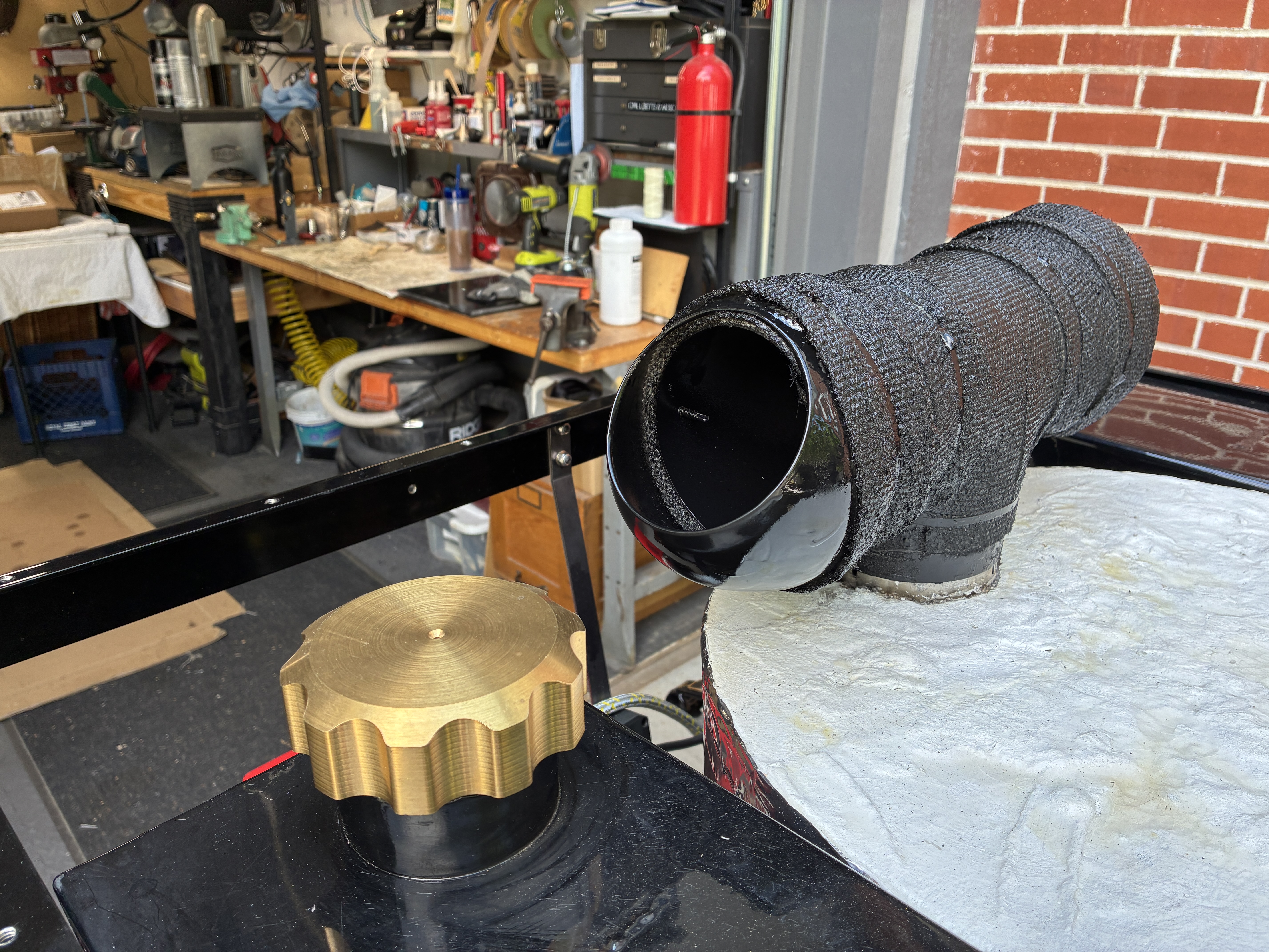


 Exhaust Pipe 

The exhaust pipe as issued by STW is a simple stainless steel "T".   It sits on the top of the smoke shield and directs the hot air out each side.  The issue with this is the it gets HOT.  I have a few concerns, the first is burns - a casual arm draped over the back of the seat could easily come in contact with the pipe.  Young children have curious fingers, and could easily get damaged.  The second is that my trunk on the rear deck could be damaged by excessive heat.

I have some pipe insulation wrap the does a very good job of isolating heat from soft flesh.   So I wrapped an initial layer and then soaked in it "water glass"  which is a very good adhesive and withstands up to 2000 degrees. 


This configuration still got hot, but did not blister the little fingers.  When I finished assembling the boiler and burner system, I noticed that the heat output did cause the water tank filler cap to get too hot to handle, so I did some Amazon shopping and found a pair of "bullnose dryer vent deflectors".  I cut these up and added additional wraps of the tape and coats of water glass.  The result is a little bulky, but not overly so. 


A good coating of black engine paint and we have a warm smokestack with the heat and smoke deflected upward.  You still do not want to stand there and stare down in but the danger is past. 


Oh Crap -  Things fell off!  

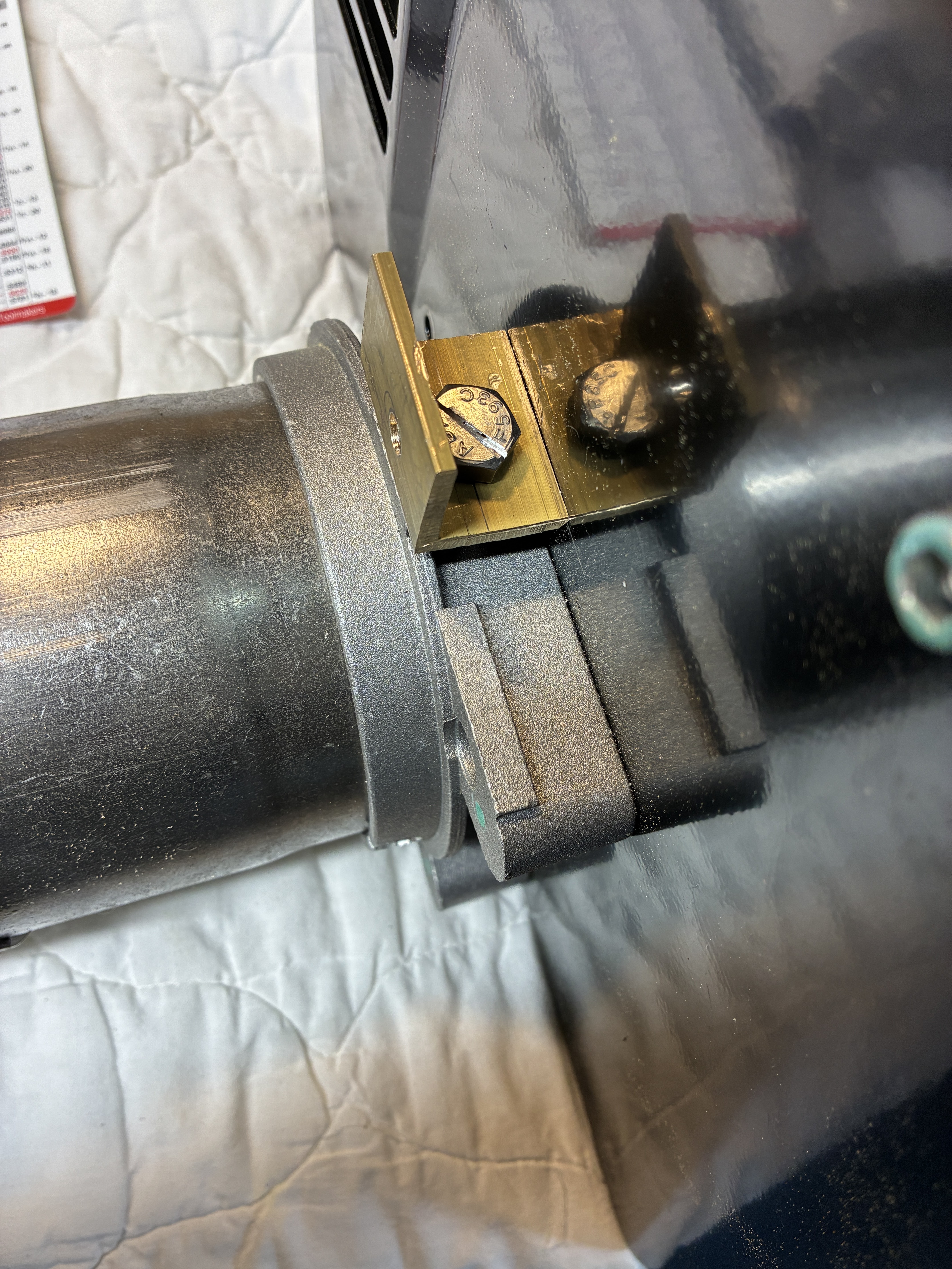
I drove her around the neighborhood a couple of times.   I usually started off smoothly, but then within a block things got a little jerky and rough.  Limped back home and put her up on stands.  While trying to avoid burnt fingers, I studied the movement of the crankwebs.  I found that the large counter-sunk flathead screw at the center of the crank shaft had started to work loose and was interfering with the movement by hitting adjacent pieces.   

Here is the low-speed study of movement: 


 Quite disconcerting to say the least.    When you look at the bolt, there is not much clearance nor is there easy access to the head so you can tighten it.  I cut off about 3/4" of a 10mm allen wrench.  Then I could fit this into the hole and turn it with a open end wrench.  I am able to get it quite tight.  So then I loosened it, and backed it out as far as I could get it.  Then I squirted some red loctite in and torqued it back down. 


 After making sure each side was tight, I painted a "witness mark" on each to watch it in the future. 


Went back out and down the street, came back home - still occasional clicks - checked the marks:


OK,  What's going on?   What could be causing the bolt to rotate?  Looking at the build drawings, I see that the crack has a square head where it is attached to the crank web.   The bolt is holding the web on the crank, but there should be no "radial" movement caused by the rotation of the crankshaft.   So it has to be something hitting/rubbing the head during rotation that is moving it.  

Doing further low-speed rotations shows that there are points where the linkages do not move smoothly, and there is noticeable in/out movement of the crank web - about 1/8".   Look harder.   

Then when I was cleaning up the driveway, I found this: 


Where the hell did that come from?   and Why?   I do not remember grub screws.   Where could that be from?   Looked around for a couple of days and then I guess I put the screw down somewhere.  Lost it. 

But why are things dropping off?   BECAUSE I FORGOT TO THREADLOCK THEM!! 

Two years ago, when I was assembling the engine,  the manual said - "do not threadlock yet until you have everything moving smoothly, but remember to do so afterward."   Guess I forgot, huh?.  

So now I went around the engine looking at the parts that should have been threadlocked.  Well, I found the problem.    


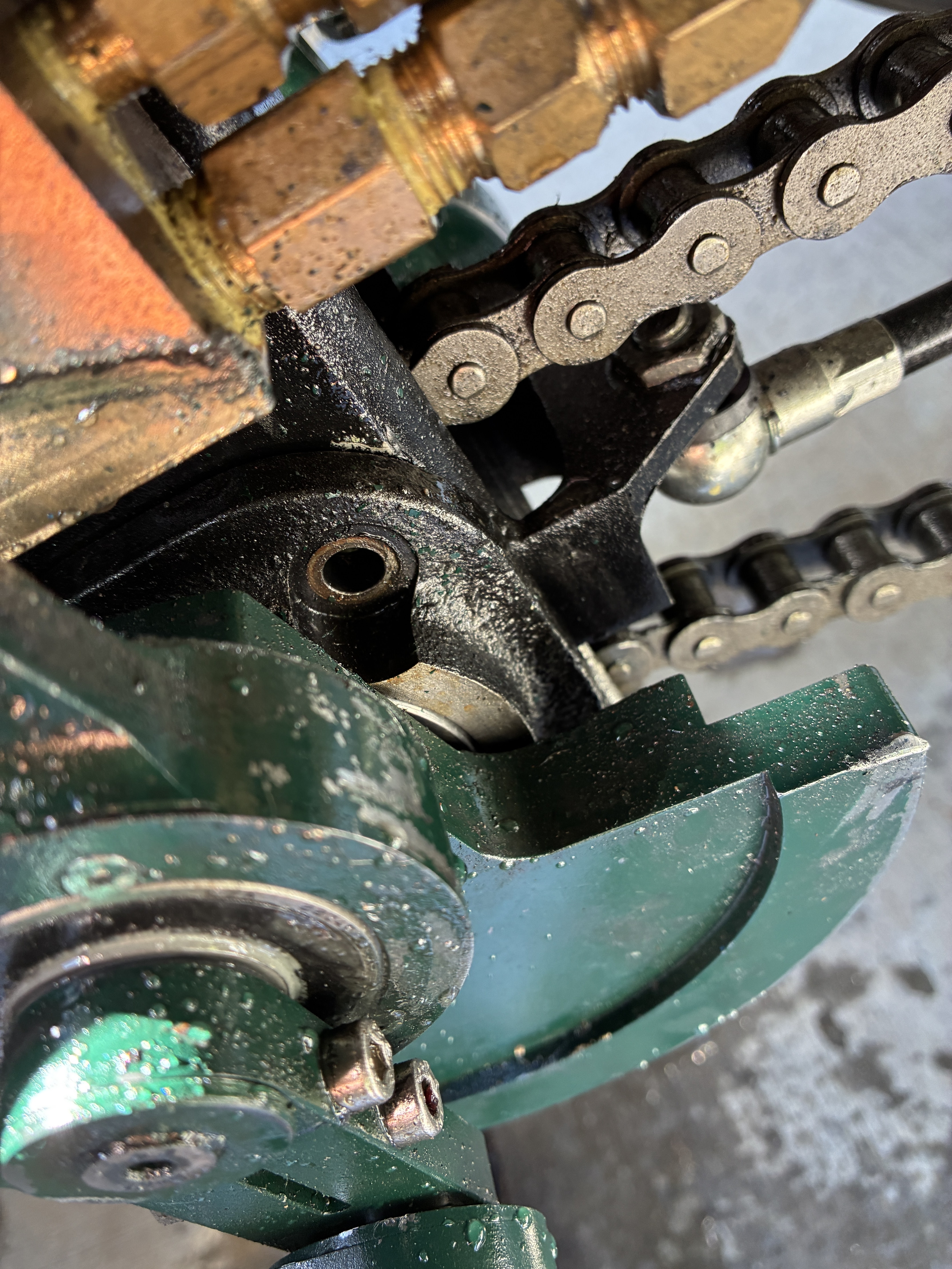
 I lost two bolts off the crank bracket and the other two are loose.  This allowed the whole bracket to shift sideways causing all the weirdness.  You can see the impact of the crank on the brass water pump housing.   Consulting the "miracle of Amazon" got me 10 - 8mm x 16mm stainless socket head bolts - overnight.   Next day I went around and after using some brake cleaner and rag to clean out the holes, I did the threadlocking I should have done before,  cranking everything down.  

While I was under the car, I looked up and inspected the drive gear.  Guess what - the missing grub screw mystery solved!!   1 missing - 2 loose - 1 still tight. 


Now that I can not find the one I had, another amazon order.  Once those come in and more threadlock applied,  I will do some more test drives.  I really want to get everything smooth before putting the sides back on.   

Doing so will complete the look, but make getting into the engine compartment that much harder.  

The next episode will cover the initial steaming experiences.  


Thanks for reading -  
Jim Pope
Denver, CO USA 

The Burner - Mounting and Adjustments

A Review

Up to now we have fully assembled the Lyka,  hooked up all the piping,  dropped in the boiler,  finished the steam connections and are ready to mount the burner and make some steam.

If you have not done this then you should drop back a couple of episodes, review the connection process and the overall build. 

So here is my baby, without the burner.  


Mounting the connecting the Reillo Burner 

The instructions from STW on mounting the burner are somewhat scant.  In addition, they tell you to RTFM and also tell you to mount the burner upside down.   Well, you need to RTFM, but you CANNOT mount the burner upside down. 

When you read the manual and documentation on the burner, you will see that it has been written for the HVAC professional and not a hobbyist like ourselves.  So there are a number of terms and conditions that may be undefined in your normal vocabulary.   

First there is the mounting process:  

The burner, when installed right-side-up, has a single bolt holding it in place.  However, the burner was not designed to be mounted on a bouncing vehicle, with the burner on its side.  The original design uses the weight of the burner to hold the seal tight against the mounting plate.  When you put everything in a 90degree rotation, the forces of gravity are wrong and there will be undue stress  on the mounting bolt and plate. 

To mitigate these forces, we need to fabricate a means to fasten another bolt on the opposite side from the factory mounting location.   If you turn your burner over, you will see a 10mm threaded hole opposite the mounting bolt.   There is also a hole in the mounting plate in the same location.   But they are facing the wrong ways.   You need to make a "L" shaped bracket and use two bolts to hold everything in place.

This is a really tight spot to work in.   Here is a picture of me holding a piece of brass angle in place while trying to figure out the way that works best: 

   The factory bolt is at the top, my finger is pointing to the location of the added bolt. 

 The trick here is how to get access to one of the connections in order to remove the burner in the future. I chose that the connection to the mounting plate should be "permanent" and the bolt into the burner should be removable.   The bracket will have a countersunk bolt into the mounting plate and then I will use a bolt with a slot cut into the head for fastening the burner. 


The mounting plate also must be modded a little.  You need to cut away for the bolt head on the support strap.  Both the friable gasket and the mounting plate need to be cut away to clear the bolt.  I managed to make a mistake and cut the wrong place on the plate.   Finally, make sure you use the 1/2 height nuts and cut off the excess on the plate bolts, otherwise you will have some obstruction when you mount the burner. 


If you look carefully on the right side you can see the head of the countersunk bolt holding the bracket in place.  


When mounted, it only takes a moment to tighten the two bolts.  Here are views from the top ab both sides of the installed burner. 


Mounting the Inverter. 

STW provides a bracket to hold the inverter.  They have the habit of mounting things to the inside of the body panels.  I do not like to do this, so I decide to follow Grier's example (again) and provide an additional structural member to hold the bracket. 

I start with a piece of aluminum angle from the scrap pile. 

Painted and mounted.
 

Countersunk mounting holes and on goes the bracket - 


STW provides some foam tape.  This goes on the inner edges of the bracket to help absorb shocks.  The power cables from the control box connect to the terminals on the lower end of the inverter.  The power plug to the burner goes into the other end. 

The first time I connected power to the inverter from STW it blew a 30 amp fuse.  Not good.  I checked it out further and determined it was indeed an "out of box failure".   STW sent me another.   But in the meantime, I ordered a similar model off the web.   They are probably from the same Chinese factory. 


In the picture above you can also see the fuel line connection to the fuel filter.  More on that later. 

Wiring the burner to the inverter. 

The burner comes from the factory with a pre-wired pigtail cable.  When you open up the end of the pigtail, you can see where the connections are made and where you will need to connect wires on the cable coming from the inverter.   


This is where living over here in the USA can be a detriment to common sense.   We are on a 110V 60hz standard.  Most of our electrical devices run at 110V and we look at 220VAC as something that powers major appliances like stoves, hot water heaters,  and other high current items.  While we might get an occasional shock at 110, the 220 feeds are avoided with fear.     

In our circuits, we have 2 - 110v legs and a neutral (ground),  so when I see a diagram like that below showing 230V with just a L(ine) and N(eutral) my brain rebels. 
 

Looking at the diagram above, it took a minute to figure out that the successful firing only requires Line voltage at the T2 connector.   That is because the connection at 1 (line) gets looped out to T1, routed thru thermostats and switches and back into T2.  Since we do not have thermostats, we can just connect to T2 directly when we want the burner to fire.   

STW provides a short piece of power cable, the larger multi-plug end and the 3 prong connector.  The 3-Prong connector has a built in fuse (15A).  You just have to trim each lead to length and make sure the screws are all snugged down and tight.


The multi-socket end can be mounted to the support bracket by either drilling some holes and using supplied bolts or, as I did, you can use the super heavy duty 3M double sided tape to fix it in place. 

Then plug the 3-prong end into the inverter.  Leave the power switch on the inverter in the OFF position for now. 


Fuel Line and Filter 

In the pictures above, you can see the braided fuel line coming from the fuel filter.   The complete fuel system should be in your shipment from STW.  This would include a Tank outlet connector, the 1/4" copper fuel line, the metal - cleanable fuel filter, and the connectors for the inlet and outlet of the filter.  

The outlet of the filter and the braided line from the filter to the burner are provided with the burner.  However in my shipment I was missing the inlet port to the filter. Also - I did not know that the outlet port was inside one of the misc parts bags in the burner box.  

So since I wanted to make some other changes, I decided to make the 1/4" copper connections compression.   My first change in design was to acquire an on/off valve for the fuel tank exit port.


Actually it is an On/Off/Drain valve.

The fuel line is routed thru all the other piping and comes very close to the Flame Shield.  So close infact that I worried about excessive heat.   I later protected it in a heat-wrap to avoid issues. 


Adjustments that need to be made. 

When the Riello’s ship, they are setup for Kerosene as a fuel.  If you use these settings for diesel you will be under-powering the burner and it will not put out decent heat, lowering the overall efficiency of the boiler and steam output. 

In the manual, toward the back, is a table with the settings.    Table E. 


We have a nozzle rated at 2.00GPH and 60 deg.    The marker above shows the default settings.  
 
Below are the settings for diesel.  

 
The three settings are: 
Pump Pressure
Combustion Head
Air damper

The easiest is the Air Damper. 


It comes in at 3.3,   You need to set it to 5.0.  You loosen two screws and rotate it until the little arrow points to 5.0

Make sure you tighten the screws again. 


The combustion head is weird.  
 
I can not figure out how to make the adjustments from the 
way the manual explains them.   I was able to “reverse engineer”  a way to set the opening. 

On the chart,  we can see that the initial settings is at 2.5, and we want to end up at 5. 
So we need to increase the setting by another 2.5.  I think this is mm but I am not sure. 

Looking at the manual - 

 
Look at the lower section:  
The last sentence says:” One set point corresponds to three (3) turns of the rod. A hole 
(in one of the faces) will facilitate counting the number of turns."   
 
Since we need to move 2.5 set points, this would be 7 1/2 turns of the knob.     
The picture below shows the knob. 

 
It’s hard to see but on the burner there are markings to direct you for + and -.   This sets the combustion chamber settings. 


The last parameter is the pump pressure.   
 
In the chart this is to be set to 12Bar or ~175psi.
 
There is a panel on the burner that has two features: 
An adjustment screw and a port with a bolt in it. 

 
You need a pressure gauge.   Any one will do as long as you can get to 175psi (12Bar).
The port is 1/8BSP so you might need an adapter.     My rig can be seen below.
I added a valve (just because) and adjusted the screw until I got to 175psi.  


You have to do it while the  burner is running.   BUT WAIT!!  

So you had probably better hook up the fuel line.  In the picture above, right above the end of the fuel line, you can just see the edge of a YELLOW plastic plug.  It is the only one on the burner.  This is where the fuel line attaches.  
 
You need to get fuel line "primed" by sucking some thru it. I added a short piece of clear tubing to the end and then sucked until I could see the fuel appear.  Then I applied a bit of thread sealant and screwed in the fuel line.  
 
Since you waited until you had all the pipework done before you got to this point, you should be able to put some water in the boiler.  You just need a couple of gallons in there to keep from scorching the boiler.  You can use the filler hole in the top and a small funnel to get some in.  Only the lower connections (drain-down and lower sight glass connection) need to be in place or temporarily plugged.
 
NOW YOU CAN FIRE THE BOILER AND ADJUST THE PRESSURE. Use a screwdriver to move the adjustment to about 175 PSI (12 Bar). Clockwise increases the pressure, it might take a couple of turns.  

This concludes the settings for the burner. 

Important notes:
 
1. Even though people say that you can fire the boiler for a short (15-20 sec) period without water - DO NOT do that.  Do not risk the boiler for a quick test.  put a couple of gallons in it and you can then test, but unless you fill it up I would limit the tests to a minute or two. 
 
2. Really study the Riello manual,  there are a number of facts in there that will enable you to understand the way the burner works.  What to do if it misfires and how to clean it when you do maintenance.  
 
Thanks for reading, 
Jim Pope
Denver, CO USA