
Prepping the Frame and Panels
The frame was assembled 2 years ago. The welded tabs and pieces determined the angles and position of the major pieces. It is a tribute to STW that the pieces came together and actually line up pretty well with the newer bits and the panels fit incredibly well.
The color scheme will be Glass Black with British Racing Green (BRG) accents. There will be some add-ons in the area of side louvers and back panel. I have also engaged a local Pinstripe Artist (Pinstriping By Brock) to add the embellishments on the frame and sides after he gets back from Sturgis. For those reading this that are not in the US, Sturgis is a yearly gathering of motorcycle clubs and riders that happens every summer in Sturgis, South Dakota. https://www.sturgismotorcyclerally.com/
I have already covered the creation of louvers in a previous post, Oct 2023. Now I need to build the rear panel and get ready to add the louvers to the side panels.
There are some drawings available that lay out the measurements on Locomobiles for the panles and louvers, as well as beading and decorations. So first I found the one on the rear panel.

Then I laid out the dimensions on the main rear panel.

After a couple of coats of primer, I painted the back of the panel (just the edges) and then fitted it to the main rear panel. There are cutouts for the burner and also the cable from the License Plate/Tail Lamp.


Waiting for a final finish coat. Following the rear panel painting, it will be laminated (somehow).
Deck Preparation
The deck is in two pieces, the front piece is under the seat and pretty much hidden from view. I cut out around the water tank sensor location, and used flat head screws to mount the deck to the frame. Then I figured out the location for attaching the seat. I screwed the seat thru the frame member in two locations, and also thru the deck alone (with nuts) in another two. Once the deck is painted, I will be coating the underside of the seat with a special teflon tape that will keep the damage to a minimum during removal/replacement as a part of exposing the engine for maintenance.


Bolts for Deck Mounting
I did a quick poll on Facebook to see what bolt type I should use.
There are three possible concepts:


Most people felt the Crown Nut looked the best. However, it also presented the most difficulties. In order to use the nut, you have to have a bolt or stud. Since I need to be able to disassemble all the panels in order work on the engine and piping, I was very hesitant to have a bunch of studs sticking up/out where I would get snagged.
So I came up with a concept, more on that later. First was to locate bolt-holes. Some were easy, as there were pilot holes in the frame already. The holes were exactly the size I needed for 1/4x20 bolts. I ordered a selection from my favorite place, McMaster-Carr. Then I went around and hand-tapped all the pre-existing holes.

Then I held the panels in place and marked from the back-side. After drilling with a pilot and slip-fit size bits, I was able to temporarily hold up the panels in place, verify alignment and relationship with adjacent pieces. After that I could measure and drill down thru the frame member for the top deck panels. I tapped a few to hold the panel so I could finish up.


I also started to locate accessories on the body as well.
The Rear Lighting
The rear lighting is made up of three pieces, the License Plate Lamp and Bracket and the two Duo Lamp brake and tail lamps. I started by adding the License Plate unit (an LED converted Never-Out), and located a hole for the cable to pass. Then I made a couple of lamp brackets for the Duo units and did some tests for the circuits.


I cut a template for the Duo-Lamp bracket. Then cut the brackets out of some scrap fiber-board. I will be painting them black.


Tail Lights - Duo and License Plate.


NOTE: If you have been following this blog, you will see that sometime I am a little out of order. I guess I have some A.D.D. and jump around a bit. So I go back and bring things into a "Topic" orientation to make things a little more sane. Case in point - go back one posting and you will see the front panel all finished, yet in the pictures above I have barely started it. That is because I was waiting on the results of the poll on "Bolt Heads"
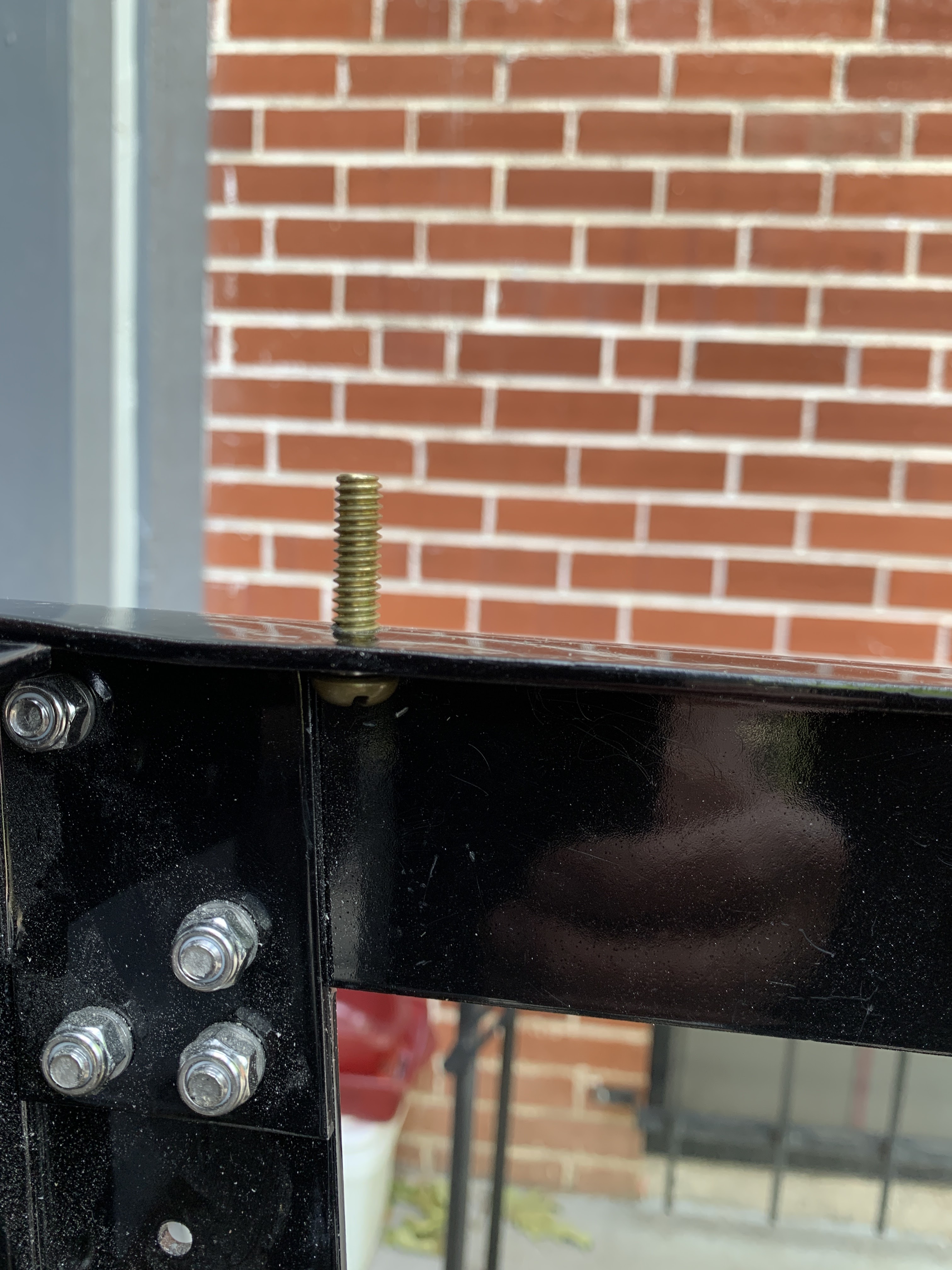
Crown Bolt Heads
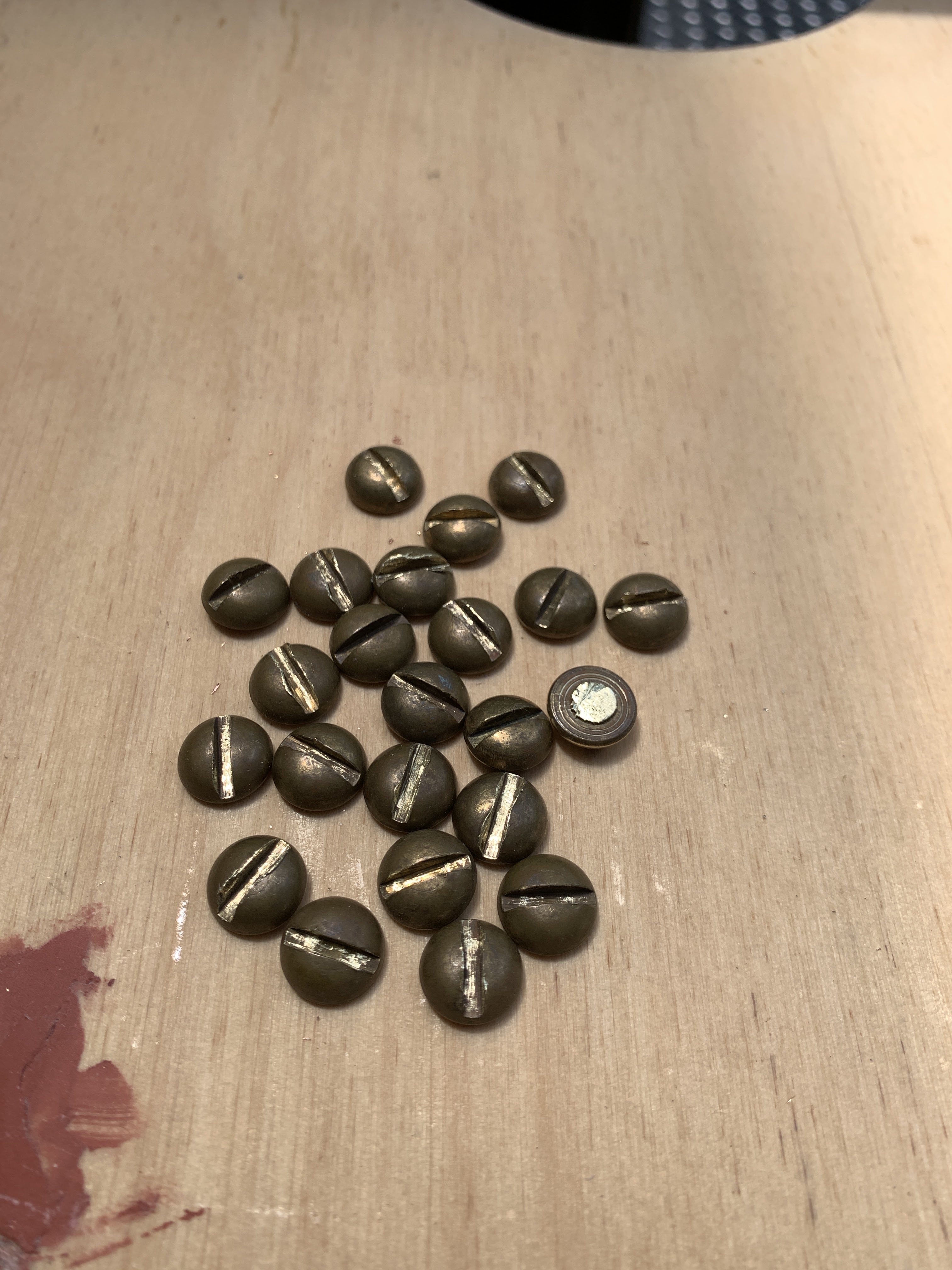
Before moving on to the side panels, it is time to finalize the bolts. The results of the polls are that most like the look of Crown Nuts. So I needed to figure out the best way to use them. I hit upon a method of making "Crown Headed Bolts" Such a thing does not seem to exist in any hardware catalog. So I made my own.

Anyone want some extra heads?
Hole Liners
During the time of this build, I have studied blogs and talked with other builders. One of the things that popped up was that these are wooden panels. As such, they can get "squished" by nuts and bolts. They can get chipped by uneven holes and putting them on and off the frame. So a couple of builders came up with the idea of lining the bolt holes.
One builder bought tubing, cut pieces and flared one end. Then inserted the tube in the hole with the flared end out. Another builder bought special "Brass Binding Barrel Bolts" and used these to line the holes and keep the wood intact.
I chose to get some tubing. I had some copper and brass in the same size - 3/8" outside, 1/4" inside. That makes the wall 1/16". I cut the tubing to match the thickness of the panel. Then I enlarged the holes in the panel from 1/4 to 3/8 inch.
To install the tubing, I used a long bolt to make sure thinks were aligned and just snugged everything up.
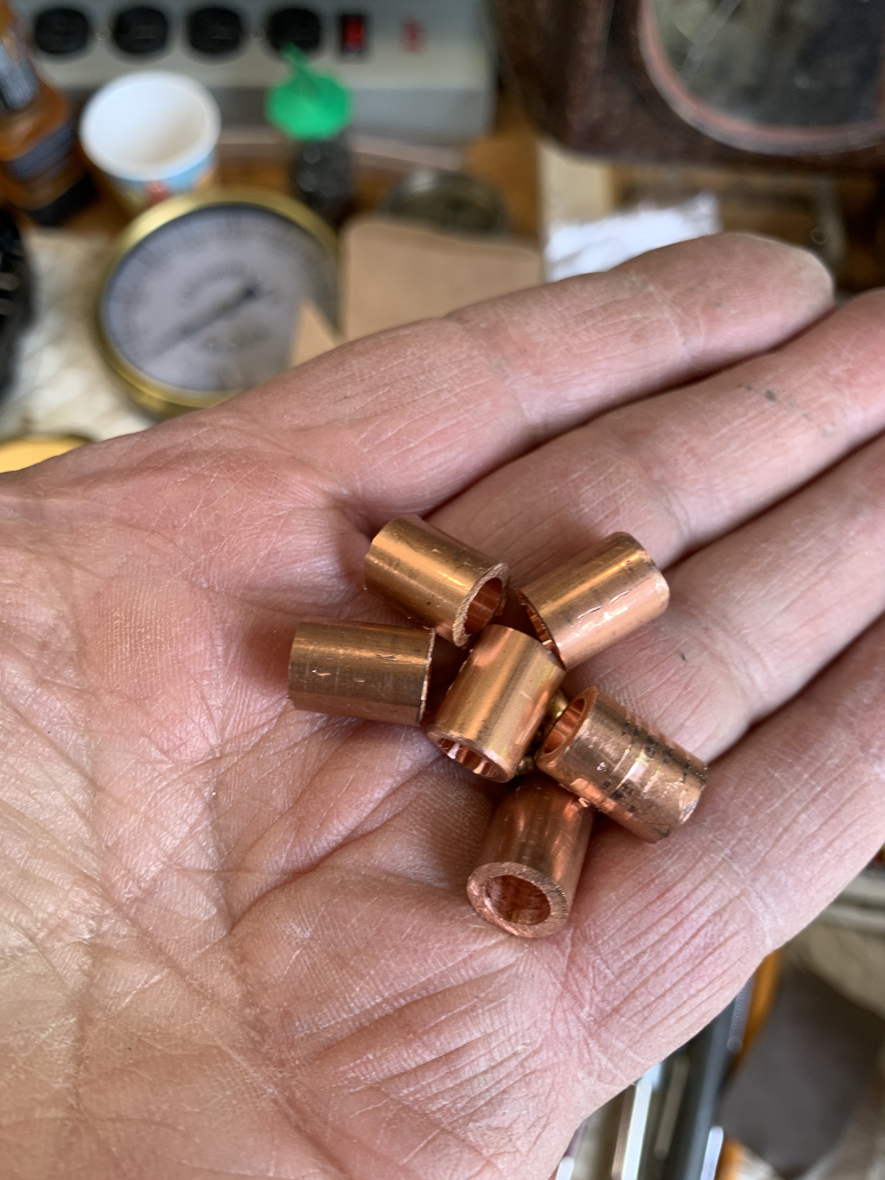
Liners ready to go


Using Screws to force the liners into place.

Side Panels


The Horn


A Last Look Before Disassembly for painting.


